LANCOM NWAPP2
aka. L-321agn Wireless (R2), L-322agn dual Wireless
This is the redesigned version of the NWAPP.
- LANCOM console port (RS-232 over mini-DIN 8-pin)
- 1x Gbit Ethernet, PoE enabled, +1 unpopulated port
- 12 V DC
- 1x mPCIe slot (for WLAN), +1 unpopulated slot
Hint for attaching the console cable: The mini-DIN end of a LANCOM console cable is roughly a cylinder, 2cm long and 1cm in diameter, whose cross-section is shaped like a half-square, half-circle. The square side should face up while plugging the cable in. On the enclosure used for the NWAPP2 and many other models of LANCOM hardware, the up side is slightly concave and has two LEDs; the down side has four feet.
Top side:
- U1: Freescale MPC8314E SoC - powerpc 32-bit, PowerQUICC II, e300 core
- U5/6: 2x NANYA NT5TU32M16EC-AC, 512Mb DDR2 SDRAM (128 MiB total)
- U22: Atheros AR8035-A Ethernet PHY
- U21: SIPEX SP3238ECA RS-232 Transciever
- U11: P16C557, PCIe® 2.0 Clock Generator
- U14/15: 2x HC 595A PHCE, Onsemi MC74HC595A: 8-Bit Serial-Input/Serial or Parallel-Output Shift Register with Latched 3-State Outputs
- U20: TI SNx4HC165 8-bit parrallel-load shit register (marked
HC165 3H6H701) - U16: TI CD54HC221 high-speed CMOS logic dual monostable multivibrator with reset (marked
HJ221 53K) - U19: TI SNx4HC74 dual D-type positive-edge-triggered flip-flops with clear/preset (marked
HC74 3C9Y501) - U17: ADI ADM708 low-cost microprocessor supervisory circuit (NOTE: the watchdog is not present in this variant)
Bottom side:
- U7: Micron 29F2G08ABAEA, 2Gb ONFI NAND flash (256 MiB)
- U10: TI SNx4LVC08A Quad 2-input AND gates (marked
LC08A 53K) - U34: TI SNx4HC4060 14-stage async binary counter/oscillator (marked
550380K HC4060)- acts as watchdog timer
- using a RC oscillator. R1=
40C(?), R2=1Ω → 1.75 kHz - the output of pin 1, 2, or 3 is selected by 10kΩ resistor placement (reset pulse?), goes to both sides of JP5
- 4.6s period (toggles every 2.3s), 1.8V
- T7 brings it to 3.6V
On a device which inexplicably forgot its firmware:
WDG:
@C@
memory test:  1 2 3 4 5  OK

Found primary and mirror bbt

NO VALID FIRMWARE!

# FLASHROM-Upload
| LANCOM L-321agn Wireless (R2)
| Copyright (C) LANCOM Systems
| Ver. 4.00.0001 / 12052014 / 132211

Start Xmodem Upload
...

Receive Error

Upload aborted
Successful boot
WDG:
@C@
memory test:  1 2 3 4 5  OK

Found primary and mirror bbt

Start firmware #1

ZLoader running..............................................................................................................................................................................................................................................................................................................................................................................................................................................................................................................................................................................................................................................................................................................................................................................................................................................................................................................................................................................................................................................................................................................................................................................................................................................................................................................................................................................................................................................................................
Outband-115200 Bit/s OK
Pressing enter after boot starts the LCOS shell.
- Booting with JP3 (
DBG) bridged drops you into a little shell. - Shorting JP5 to ground disables the watchdog.
LANCOM Systems Boot-Loader log
WATCHDOG DISABLED
Found primary and mirror bbt

NO VALID FIRMWARE!
----------------------------------------------
LANCOM Systems Boot-Loader
Version 4.00.0001 / 12052014 / 132211
Copyright (C) 2012 LANCOM Systems GmbH
 Vendor: LANCOM Systems
 Oem:
 Device: LANCOM L-321agn Wireless (R2)
 HwId:   NWAPP2
HW-Release: H, PLD-Release: --
CCB clock 133MHz, Core clock 400MHz, VCO clock 267MHz, DDR clock 133MHz LBC Clock 33MHz
Reset cause: 0

Debug-Adapter: absent
phystop: 08000000, ramfirm_end: 08000000
Minimum FW/LD version is 8.82/3.41
Active Firmware: 2
Bitrate = 115200.8N1
V<adr>/I/R/G/B/S/U/D/e/f/t/H/?>

Adr = 00000000, Len=0x80
00000000:  00 00 00 00 00 00 00 00  00 00 00 00 00 00 00 00 | ................
00000010:  00 00 00 00 00 00 00 00  00 00 00 00 00 00 00 00 | ................
00000020:  00 00 00 00 00 00 00 00  00 01 F9 E0 00 00 00 00 | ................
00000030:  00 10 00 00 00 10 73 30  00 00 8A 30 48 00 89 F4 | ......s0...0H...
00000040:  00 02 ED 10 00 00 00 04  00 00 00 00 00 00 00 01 | ................
00000050:  FE 00 00 00 FE 02 ED 10  FE 00 00 00 00 00 00 00 | ................
00000060:  34 2E 30 30 3F 00 00 00  00 FF 22 C1 00 00 00 02 | 4.00?.....".....
00000070:  00 02 ED 10 42 00 00 00  60 00 00 00 60 00 00 00 | ....B...`...`...

V<adr>/I/R/G/B/S/U/D/e/f/t/H/?>

Monitor help page
-----------------
 V<adr>  : Dump memory addresses <adr>
 G       : Start active firmware
 I       : Version Info
 U0,U1   : Upload file to Flash-ROM by XMODEM-/CRC
 R       : Reboot (Warmstart)

 Bx      : Modify outband bitrate

 E ...*  : Erase menu       * = action required
 F ...   : Firmware menu
 T ...   : Test menu
Memory can be dumped by repeatedly issuing V commands.
The test (T) menu has a few more peek/poke commands, as well as lspci.
| address | length | description |
|---|---|---|
00000000 |
128 MiB | RAM |
e0000000 |
1 MiB | MMIO (relocated by IMMRBAR) |
| address | length | description |
|---|---|---|
00000000 |
00008000 |
loader 1 |
00008000 |
00078000 |
loader 2 |
00080000 |
00f80000 |
loader spare (empty) |
01000000 |
0f000000 |
YAFFS file system |
The MPC8314E has 32 GPIOs. Their usage on the NWAPP2 board is as follows, (#) indicates active low signals:
| function | GPIO | GPIO | function |
|---|---|---|---|
| software debug mode (#) | 0 | 16 | |
| reset button (#) | 1 | 17 | |
| 2 | 18 | watchdog toggle | |
| SPI GPIO expander latch clock | 3 | 19 | |
| 4 | 20 | ||
| SPI GPIO expander CS(#) ??? | 5 | 21 | |
| 6 | 22 | PHY reset (#) | |
| PCIe clockgen reset (#) | 7 | 23 | |
| 8 | 24 | ||
| 9 | 25 | ||
| board reset | 10 | 26 | |
| 11 | 27 | ||
| 12 | 28 | ||
| 13 | 29 | ||
| 14 | 30 | ||
| 15 | 31 |
- Note that the GPIO numbers correspond to bit numbers in IBM bit order, e.g. GPIO 0 = mask 0x80000000, GPIO 18 = mask 0x2000.
- The GPIO expander doesn't actually seem to require a chip select. The latch clock is enough. LCOS interacts with pin 5 for some reason.
- Internal watchdog: write
0x556c,0xaa39to0xe000020e- This one isn't actually enabled at boot. Linux stays alive without it.
- External watchdog: Toggle GPIO 18 (mask 0x2000) by writing to GPDAT (
0xe0000c08)
The board has multiple bi-colored LEDs (A=red + B=green), which are
controlled by SPI-connected GPIO expanders. # indicates active-low.
| U14 | pin | U15 |
|---|---|---|
| LED1A (Power) | A | LED6A |
| LED1B | B | |
| LED3A# (WLAN Link) | C | LED7A (ETH) |
| LED3B# | D | LED8A |
| LED4A (WLAN Data) | E | LED18A# (Power, top) |
| -- | F | LED18B# |
| LED5A | G | LED19A# (WLAN Link, top) |
| H | LED19B# |
Note: The green part of LED7 (ETH) is directly connected to the Ethernet PHY and doesn't require any software control.
In L-321 devices, only one of the two mini-PCIe slots is populated.
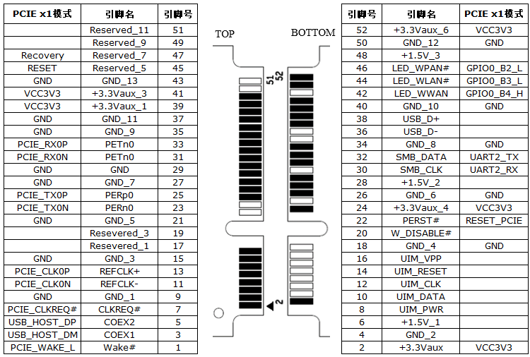
- Soldering the slot itself is fairly straight-forward, but make sure to test for continuity and shorts.
- By default, the 3.3V rail (pin 2) isn't active.
- Populate L22, which brings 3.3V
- Populate C293, C294, C295, as well as C291, C292 to stabilize the 3.3V supply
- Add some sort of mounting holes (CN19/13 or CN20/15)
- If you're going to use power-hungry peripherals such as a graphics card, make sure your power supply is up to the task
- Mini PCIe cards (e.g. the original ath9k WLAN cards) work under Linux, SATA and USB cards won't
- Mini PCIe extenders with a "USB" cable, commonly found on Aliexpress/eBay/etc. may cause a Machine Check Exception during MMIO access
Hardware prerequisites:
- RS-232 cable and LANCOM console adapter (12€ on eBay)
- 12V power supply
- Ethernet cable
Software prerequisites:
- A
powerpctoolchain. Debian'sgcc-powerpc-linux-gnupackage works fine. -
makeandpython3 - lancom-flash-tools
- My U-Boot fork, branch
nwapp2 - My Linux fork, branch
mpc83xx - Linux userspace, e.g. Buildroot, Adélie Linux or void-ppc
- Note that Adélie and void-ppc are (at least in part) built for PowerPC G3/G4, but the e300 processor in this device is based on the 603 (aka. G2).
- A console client, such as
busybox microcom,minicom, etc. - An Xmodem client, such as
sxfrom lrzsz orminicom
Building U-Boot:
-
cdyour U-Boot clone make lancom_nwapp2_defconfigexport CROSS_COMPILE=powerpc-linux-gnu--
CROSS=powerpc-linux-gnu-; make CC=${CROSS}gcc LD=${CROSS}ld - you should now have a
u-boot.binfile of roughly half a megabyte - depending on the U-Boot branch, you may also have a
u-boot.upxthat be installed directly
Building lolmon (optional):
-
cdyour lancom-flash-tools clone cd examples-
ln -spath to your U-Boot cloneuboot ./uboot.sh- you should now have a
monitor.upxfile, which includes U-Boot
Installing lolmon/U-Boot through the bootloader:
- Connect your RS-232 cable to the device
- Power it on with the
DBGjumper set - The bootloader debug menu (
V<adr>/I/R/G/B/S/U/D/e/f/t/H/?>) should appear. If it doesn't, press space a few times - Type
u1to start a XModem-CRC transfer - Send
monitor.upx/u-boot.upxto the device, through XModem and detach the console client- Example command:
sx -k monitor.upx </dev/ttyUSB0 >/dev/ttyUSB0 - Note: The previous two steps may have to be repeated a few times. At least in my setup the first transfer is unlikely to succeed (it just stops at some point). Starting a transfer and letting it time out may help.
- To get the debug menu prompt back, press space until it shows up
- Example command:
- After the XModem transfer is successful, attach the console client again
- Optionally, you can verify that your program was installed using the firmware menu (
f)
Running lolmon/U-Boot:
- Press
gin the bootloader debug menu, or power the device on without theDBGjumper - To use
lolmon, press any key within one second; otherwise U-Boot is automatically started - On the U-Boot shell, you may set various environment variables with
setenvand persist the environment in flash withsaveenv- For example, for TFTP boot you may want to set
ipaddr,serveripandbootfile - The Linux kernel command line is stored in
bootargs. Some recommended options:-
console=ttyS0: Print on the serial port -
panic=30: reboot half a minute after running into a kernel panic
-
- Automatic boot is configured through
bootdelayandbootcmd
- For example, for TFTP boot you may want to set
Building Linux:
- cd your Linux clone
export ARCH=powerpcexport CROSS_COMPILE=powerpc-linux-gnu-make mpc83xx_defconfig- optionally
make desktop.configto apply desktop defaults -
make nconfigto select additional kernel features that you need make image.fit
Booting Linux via TFTP:
- Set up a TFTP server
- Copy
image.fitinto the TFTP server's root and set it world-readable - Connect the device to the same network
- On the U-Boot shell:
-
setenv ipaddr 10.0.0.10(address of the device) -
setenv serverip 10.0.0.1(address of the TFTP server) -
tftp image.fit- Note: the filename is unnecessary if you set the
bootfilevariable
- Note: the filename is unnecessary if you set the
bootm
-
Booting Linux from NAND flash:
- Boot to Linux
-
cat /proc/mtdto verify that Linux knows the loader-spare partition - Transfer
image.fitto Linux somehow - Write
image.fitto the loader-spare partition (/dev/mtdblockN)
-
- To boot once (in U-Boot):
-
mtd read loader-spare ${loadaddr} 0 0xf00000(read 15 MiB from the loader-spare partition into RAM) bootm
-
- To configure auto-boot (in U-Boot):
setenv bootcmd mtd read loader-spare ${loadaddr} 0 0xf00000 \; bootmsetenv bootdelay 1saveenv
NOTE: If you're going to auto-boot U-Boot (without the debug jumper) make sure to keep console output at a normal level. U-Boot loglevel 9 ("debug hardware I/O") can take so long that the watchdog kicks in while U-Boot is still trying to boot.
Booting from NVMe
-
Install an NVMe disk to one of the PCIe slots (normally intended for WiFi cards)
-
Configure Buildroot:
- Enable /dev management using eudev (in System configuration)
- Enable
petitboot(in Target packages -> System tools) - Make sure that
BR2_TARGET_GENERIC_GETTYis off (Run a getty (login prompt) after boot, in System configuration) - Disable
BR2_PACKAGE_EUDEV_ENABLE_HWDBdo save a good chunk of space - Enable
e2fsprogs(in Target packages -> Filesystem and flash utilities)
-
Configure and build Linux (mostly as above)
make mpc83xx_defconfig nvme-server.configmake image.fit
-
Install Linux to NAND flash as documented above. This will act as another bootloader stage between U-Boot and the final kernel.
-
setenv bootcmd 'mtd read loader-spare ${loadaddr} 0 0xf00000; sleep 0.2; bootm' -
Boot the new
-
Boot to Buildroot and install Adélie Linux
-
fdiskandmkfs.ext4to partition the NVMe disk: 1 GiB/boot(ext4) + the rest/(ext4) recommended -
Download a rootfs and unpack it to the newly created
/partition - chroot into the new system, set your hostname and password
- install a kernel (TODO), grub (
- reboot
-