Roku 3
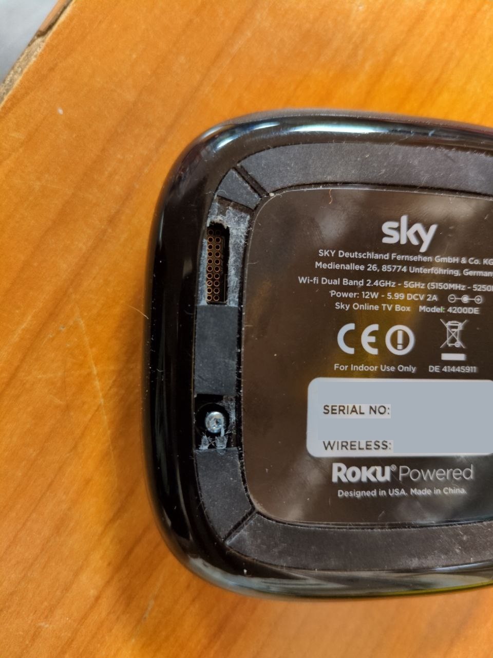
I recently (2026-01-24) picked up a Sky-branded Roku 3 set-top box.


Ports:
- DC power, 6V/2A (barrel jack), "Reset" button
- HDMI output, MicroSD, USB A
- 10/100 Mbit Ethernet, 2.4/5 GHz WiFi
- Status LED, Infrared receiver
Chips:
- U1: Broadcom BCM11130 SoC, VideoCore 4, ARM Cortex-Asomething
- U2, U3: 2x Samsung K4B2G16460-BCK0, 16 bit, 2 Gbit DDR3 RAM
- T1: Mingtek HN16012CG, 10/100 Base-T Single Port Ethernet transformer
- U24: Broadcom BCM5241 Ethernet PHY
- U30: TI TPS65270, Converter with 4.5V to 16V Input Voltage, 2A/3A Output Current
- U9(?): Toshiba IC58NVG1S3ETA00, 4 Gbit (512M × 8 bit) CMOS NAND E²PROM
- U28: TI 2051B, current-limited power-distribution switch
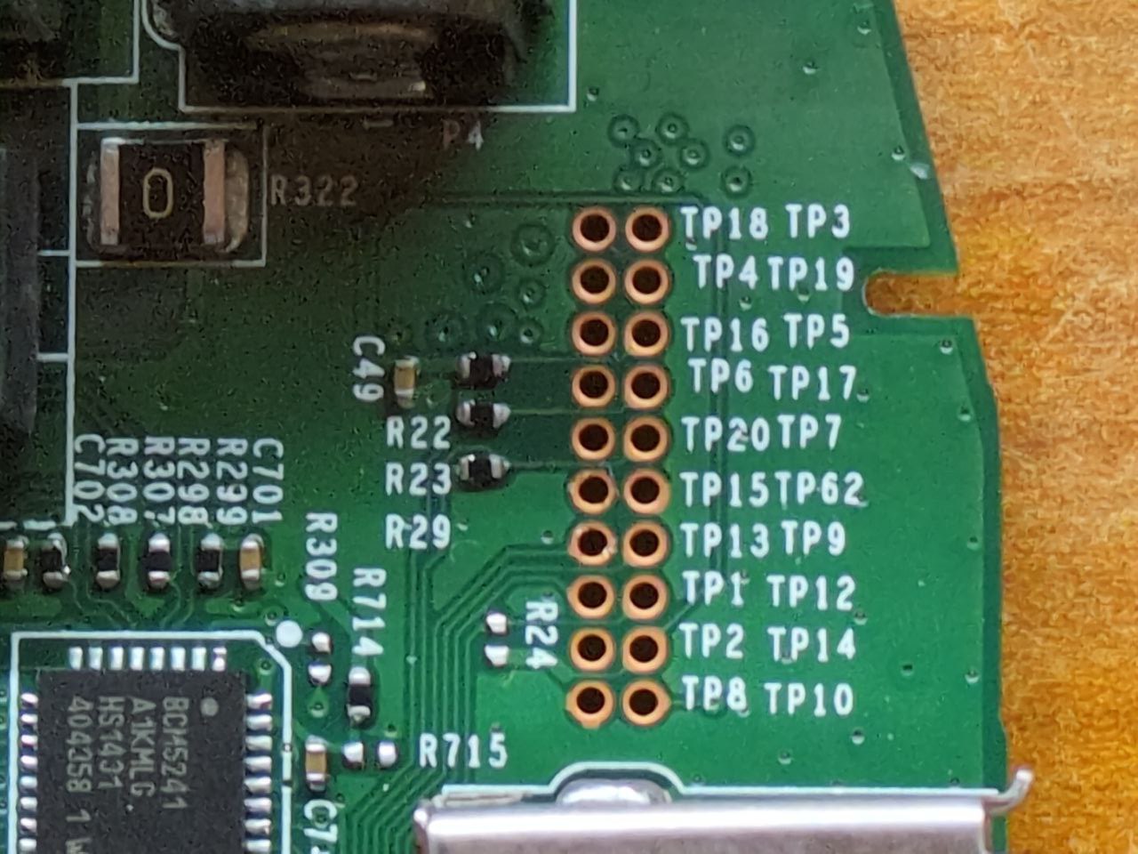
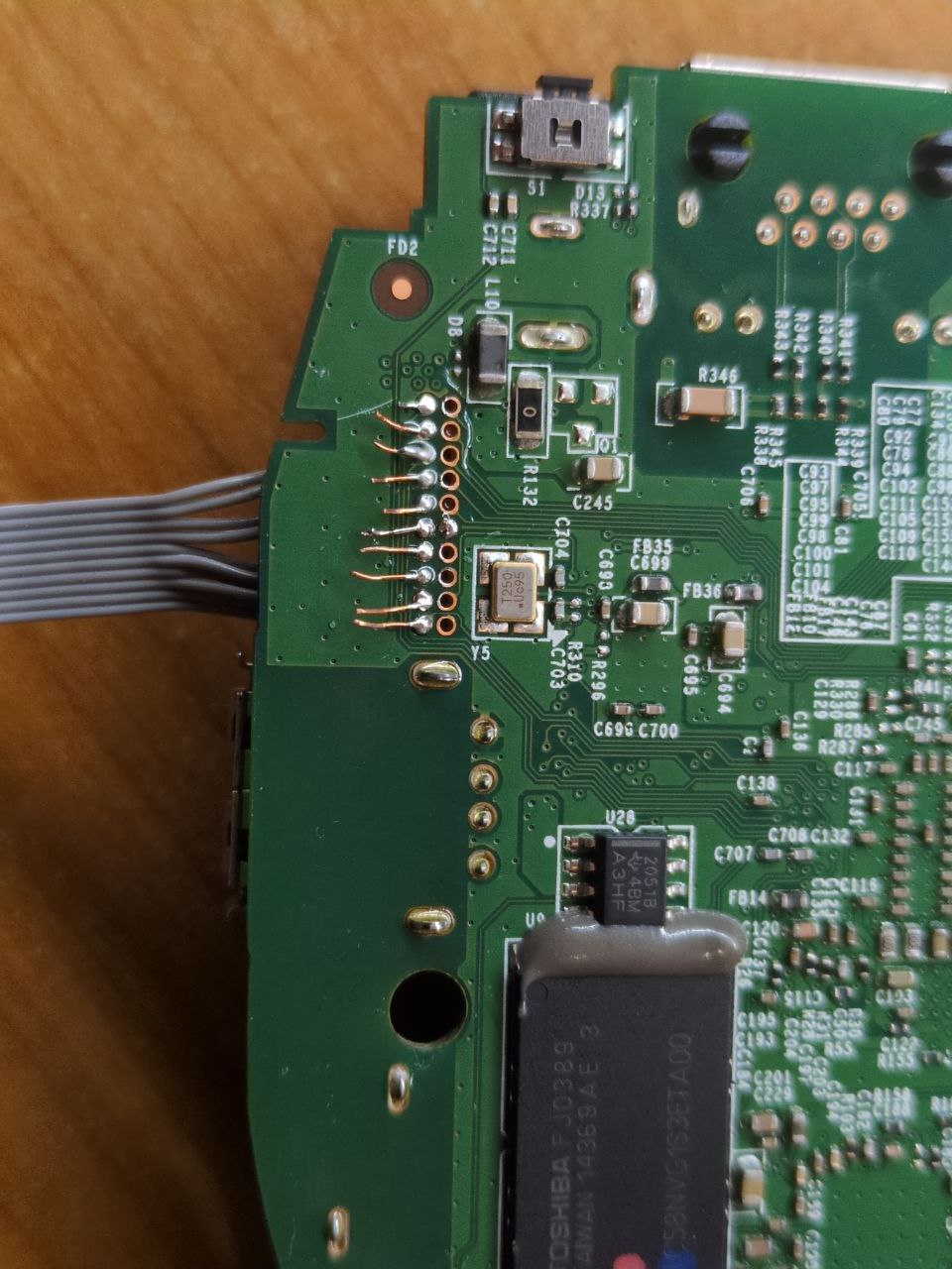
The underside has a ring of rubber, so I felt for holes in the plastic beneath the rubber. I found three screws (as expected), and one debug port: a 2x10 array of test points, all of which are labelled.
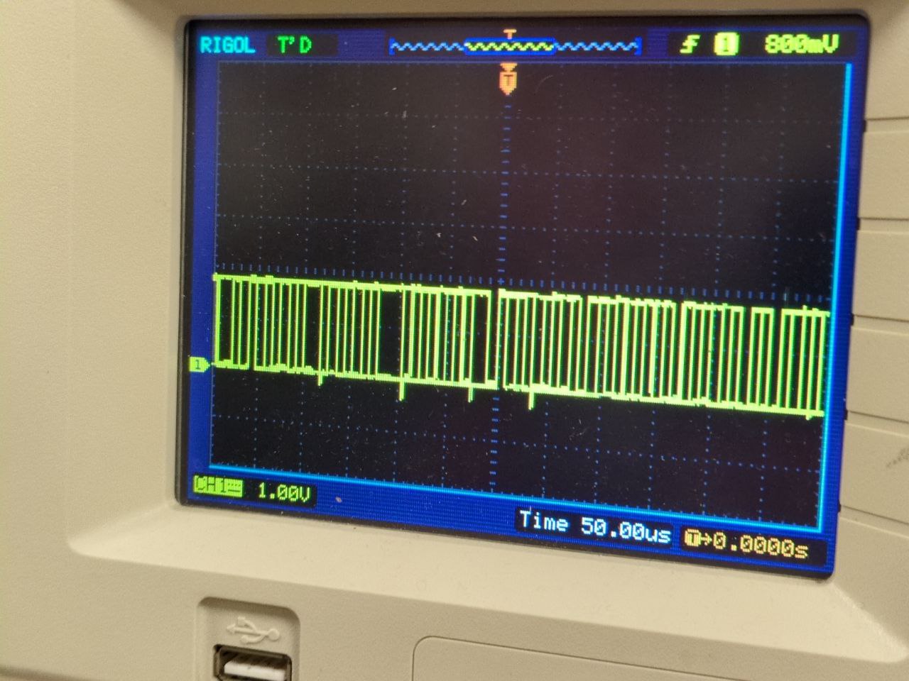
I probed around and found an interesting signal on TP13.
The signal had 1.8V of amplitude, a regular and pretty square-like waveform, and a bit rate of about 6 per 50 µs, which comes out to 120000 baud, close enough to the typical 115200.
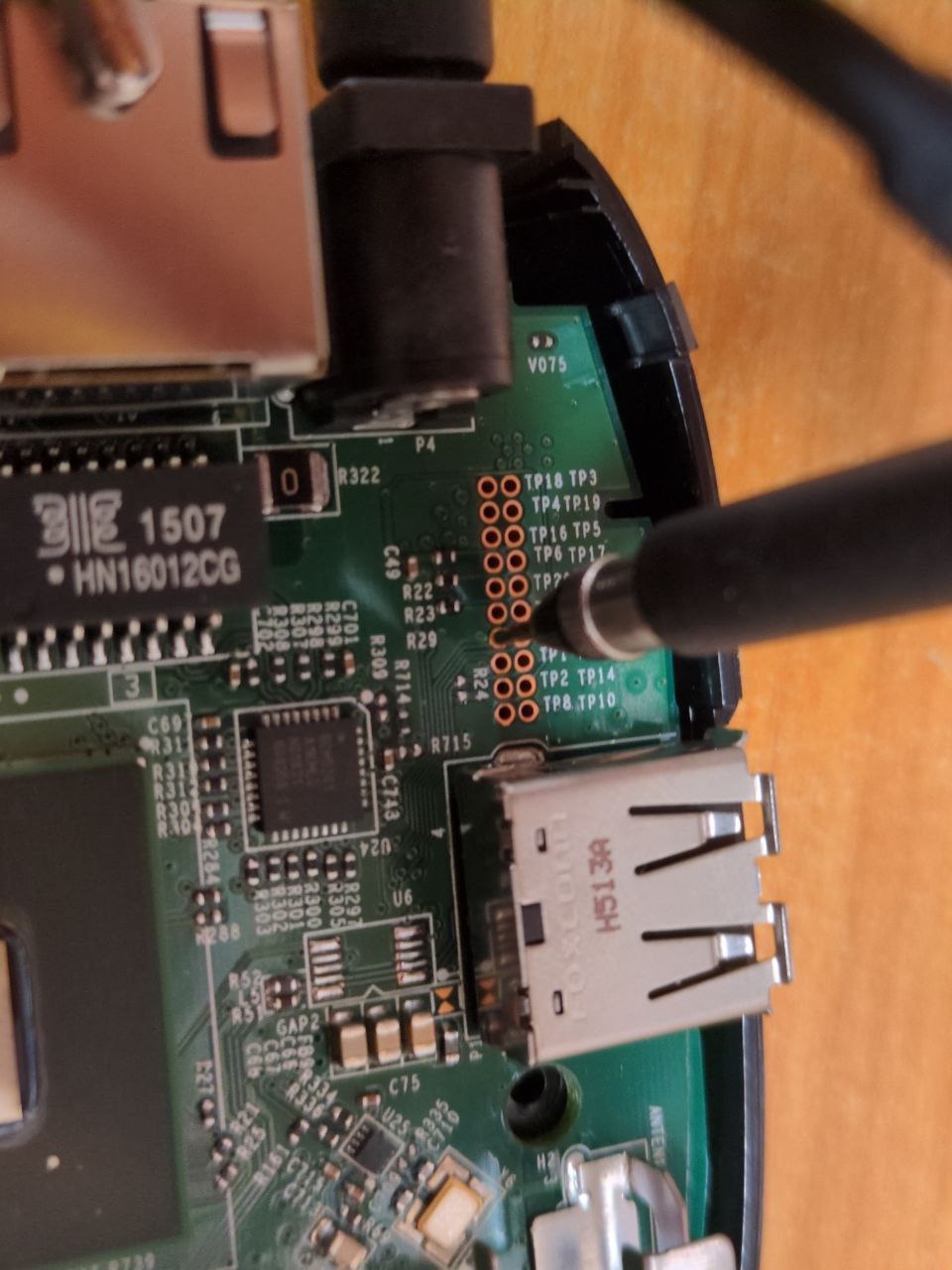
Additional photos: rubber feet exposing the debug port, probe attached to TP13
Thanks to the Glasgow Interface Explorer's level shifters, I could faily easily capture the boot log:
boot log
********************************************************************************
CAPRI Loader (version = 0.2) started. Built date: Aug 31 2012 Time 17:21:35
********************************************************************************
+bootldr_flash_init
NAND Page Size: 2048, 64
Loading image!
Attempting SDCard_Load.
reset the host controller, status 0x2
reset the host controller, status 0x3
CBOOT_Flash_init failed.
reset the host controller, status 0x3
reset the host controller, status 0x3
CBOOT_Flash_init failed.
SDCard_Load: 1
p1 starts at 16
p2 starts at 400
ver: 5, 6
Reading: 209
Checking: 427104
hash: 97 54 4a 90 f3 57 12 01 c3 c5 91 d3 13 3d dd 07 ff 0e e4 27
Image valid.

********************************************************************************
CAPRI Preuboot (version = 0.1) started. Built date: Mar 30 2021 Time 13:05:47 (29320)(99500)
********************************************************************************
OTP h/w initialized successfully
in[0] = 7004fa76
in[1] = 78a6baf9
in[2] = 088db2ce
in[3] = 01647174
in[0] = 00000000
in[1] = 11111111
in[2] = 22222222
in[3] = 33333333


U-Boot 2011.06 (Mar 30 2021 - 13:05:55 UTC) - bcm11130_roku_austin

I2C:   ready
DRAM:  384 MiB
Relocation Offset is: 0x18236000
NAND:  ReadConfigValid: valid configuration

NAND 8 bit, ECC enabled
ID 98DA901576140300
banks 1
bank size 256 MB
page size 2 KB
block size 128 KB
aux data size 8 bytes
used oob bytes 64/64
main data ecc 8/512
aux data ecc 0/8
timing_select 2
timing mode 4
NAND read of geometry page succeeded
NAND: Remapping Bad Blocks:
NAND: Remapping Active partition using BBT 0x031e1000
block_map:
[1]1
256 MiB
MMC:   KONA SD/MMC: 0, KONA SD/MMC: 1
secure; no flashIn:    serial
Out:   serial
Err:   serial
Card did not respond to voltage select!
MMC init failed
Auto-detected LDO daughtercard

CPU Info:
    Freq ID  =    7
    Cpu freq =  897 MHz
    AXI freq =  299 MHz (Cpu freq divided by 3)
    ndiv_int=69 pdiv=1 mdiv=2 pl310_div=3

Setting L2 MMU table for boot ROM -- not set in SWDEV mode
Core 1 patch function addr: 0x9fe46774
Core 1 patch function end addr: 0x9fe467b0
Core 1 patch SRAM loc: 0x3404bf00
   ******************
   Type: DDR3
   Jedec: DDR3-800E
      CL: 6
      CWL: 5
      WR: 6
   Chip Width : 16 bits
   Bus Width : 32 bits
   Rank : Single
   Each Chip Size : 2Gb
   Total Bytes: 0 MB
   Clock Speed: 399999994 Hz
   ******************
mtdparts variable not set, see 'help mtdparts'
mtdparts variable not set, see 'help mtdparts'
Application image detected
check image in partition 0
Partition 0: Verify uimage: Success
Partition 0: Verify firmware: Success
VC4 raw image detected
Enabling VC4 JTAG
Assigning GPIO CAM1_PWDN (8) to VideoCore as an OUTPUT.
Booting VideoCore at 0xc0000200.
Booted VC ok!
partition 0: OK
custom_pkg info: This file is 3rdParty/custom_pkg/austin/skyd/common/boot/info

booting kernel
Application image detected
Broadcom BCM11140 Ethernet driver 0.1
port 0 PHY ID: 0x0143, 0xBC31
BCM5241 has no required initialziation
bcm11140_eth-0
## Booting kernel from Legacy Image at 9f54cd28 ...
   Image Name:   Linux-3.0.82-grsec
   Image Type:   ARM Linux Kernel Image (uncompressed)
   Data Size:    3759088 Bytes = 3.6 MiB
   Load Address: 88008000
   Entry Point:  88008000
   Verifying Checksum ... OK
   Loading Kernel Image ... OK
OK
loadaddrstr = '9fea08dc' loadaddr=0x9fea08dc
Setting up dt-blob tag ...@0x880001ac from 0x9fea08dc
dt-blob size: 5361 bytes
Done dt-blob tag, 0x880016a8

Starting kernel ...

Uncompressing Linux... done, booting the kernel.
66666666666666666666666666666666666666666666666666666666666666666[...]
It starts with a "CAPRI Loader" and a "CAPRI Preuboot", which seems to
initialize some PLL or something (potentially for the DRAM controller).
Then, U-Boot is started, reporting 384 MiB of RAM (out of the 512 one could expect -
the board has two RAM chips of 2 Gbit each). Quite nonchalantly it announces:
Enabling VC4 JTAG and Booting VideoCore at 0xc0000200.
The Broadcom VideoCore 4 is the GPU subsystem that is also used in Raspberry Pis, but this is a different SoC, the BCM11130.
Finally U-Boot loads Linux. There's no explicit indication that one could interrupt the boot flow.
After Linux is loaded, it keeps printing 6, about 30 KiB of it until I
aborted the capture. The leading theory is that they patched the UART driver to
always print 6 instead of whatever character should actually be printed.
I guess they don't want curious eyes on their digital content distribution system.
Some differences can be observed when the box is booted with a µSD card inserted
--- boot.log 2026-01-23 23:28:39.503777445 +0100
+++ boot-sd.log 2026-01-24 19:12:10.753524834 +0100
@@ -1,4 +1,4 @@
-ÿÿ
+ÿ
********************************************************************************
CAPRI Loader (version = 0.2) started. Built date: Aug 31 2012 Time 17:21:35
********************************************************************************
@@ -7,12 +7,8 @@
Loading image!
Attempting SDCard_Load.
reset the host controller, status 0x2
-reset the host controller, status 0x3
-CBOOT_Flash_init failed.
-reset the host controller, status 0x3
-reset the host controller, status 0x3
-CBOOT_Flash_init failed.
-SDCard_Load: 1
+Power setting offset=0x28, value=0xf00
+SDCard_Load: 3
p1 starts at 16
p2 starts at 400
ver: 5, 6
@@ -64,8 +60,6 @@
secure; no flashIn: serial
Out: serial
Err: serial
-Card did not respond to voltage select!
-MMC init failed
Auto-detected LDO daughtercard
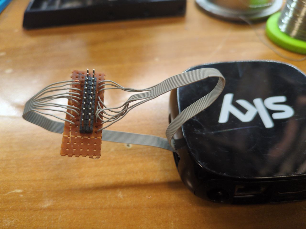
CPU Info:Considering the prospect of a JTAG port, I soldered the whole debug connector.
Photos: after soldering one row and after soldering everything.
Glasgow's JTAG applets quickly found the JTAG pinout (jtag-pinout) and told
me what it is (jtag-probe, arm-debug):
Glasgow detection logs
$ glasgow run jtag-probe -V A=1.80,B=1.80 --tck A4 --tms A7 --tdi A6 --tdo A3 --trst B7
I: g.hardware.device: generating bitstream ID bd88e1d25e2999bfbafc94c7719e710e
I: g.hardware.assembly: port A voltage set to 1.8 V
I: g.hardware.assembly: port B voltage set to 1.8 V
I: g.cli: running handler for applet 'jtag-probe'
I: g.applet.interface.jtag_probe: shifted 32-bit DR=<11101110001000000000010111010010>
I: g.applet.interface.jtag_probe: shifted 4-bit IR=<1000>
I: g.applet.interface.jtag_probe: discovered 1 TAPs
I: g.applet.interface.jtag_probe: TAP #0: IR[4] IDCODE=0x4ba00477
I: g.applet.interface.jtag_probe: manufacturer=0x23b (ARM Ltd) part=0xba00 version=0x4

$ glasgow run debug-arm -V A=1.80,B=1.80 --tck A4 --tms A7 --tdi A6 --tdo A3 --trst B7
W: g.applet.debug.arm.jtag: applet is PREVIEW QUALITY and may CORRUPT DATA
I: g.hardware.device: device already has bitstream ID bd88e1d25e2999bfbafc94c7719e710e
I: g.hardware.assembly: port A voltage set to 1.8 V
I: g.hardware.assembly: port B voltage set to 1.8 V
I: g.cli: running handler for applet 'debug-arm'
I: g.applet.debug.arm.jtag: AP #0: IDR=0x44770001
I: g.applet.debug.arm.jtag: designer=0x23b (ARM Ltd) class=0x8 (MEM-AP) type=0x1 (unknown) variant=0x0 revision=0x4
I: g.applet.debug.arm.jtag: AP #1: IDR=0x24770002
I: g.applet.debug.arm.jtag: designer=0x23b (ARM Ltd) class=0x8 (MEM-AP) type=0x2 (unknown) variant=0x0 revision=0x2
I: g.applet.debug.arm.jtag: AP #2: IDR=0x14760010
I: g.applet.debug.arm.jtag: designer=0x23b (ARM Ltd) class=0x0 (none) type=0x0 (unknown) variant=0x1 revision=0x1
I initially expected to find the barely-documented VPU JTAG interface, but to
my pleasant surprise it's a relatively normal ARM JTAG (IDCODE=0x4ba00477),
exposing two MEM-APs and one JTAG-AP:
| AP | IDR | class | type | comments |
|---|---|---|---|---|
| #0 | 0x44770001 |
8, MEM-AP | 1, AHB | main memory access |
| #1 | 0x24770002 |
8, MEM-AP | 2, APB | supposedly Coresight Private Peripheral Bus |
| #2 | 0x14760010 |
0, none | 0, JTAG-AP | OpenOCD complains about missing dbgbase |
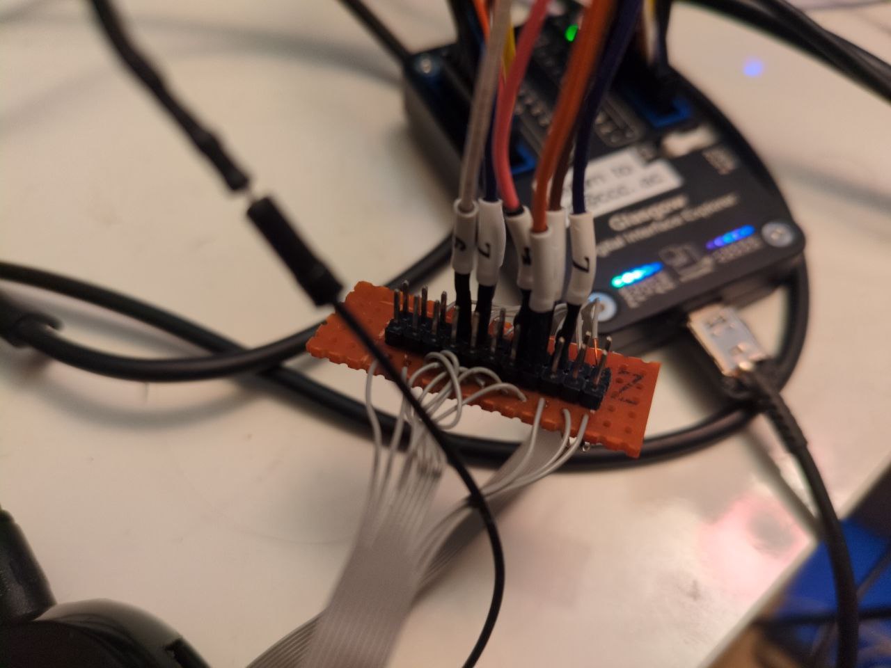
I set up Glasgow to connect to the UART and the JTAG port at the same time:
glasgow multi jtag-openocd -V 1.8 --tck A4 --tms A7 --tdi A6 --tdo A3 --trst B7 tcp:localhost:9999 \
           ++ uart --rx A0 socket tcp:localhost:2222
Thanks to a blogpost on starlabs.sg, I got some info out of OpenOCD.
OpenOCD config and output
config:
gdb_port

adapter driver remote_bitbang
remote_bitbang port 9999
remote_bitbang host localhost
#remote_bitbang use_remote_sleep on
adapter speed 10

set _CHIPNAME bcm11130

reset_config srst_only

jtag newtap $_CHIPNAME cpu -expected-id 0x4ba00477 -irlen 4
dap create $_CHIPNAME.dap -chain-position $_CHIPNAME.cpu
$_CHIPNAME.dap apcsw 0x200000

target create $_CHIPNAME.ahb mem_ap -dap $_CHIPNAME.dap -ap-num 0
target create $_CHIPNAME.apb mem_ap -dap $_CHIPNAME.dap -ap-num 1
target create $_CHIPNAME.cpu cortex_a -dap $_CHIPNAME.dap -ap-num 2
#target create $_CHIPNAME.cpu cortex_a -dap $_CHIPNAME.dap -coreid 0 -dbgbase 0x3fe12000
init

targets $_CHIPNAME.ahb
info about APs:
Open On-Chip Debugger
> dap info 0
AP # 0x0
		AP ID register 0x44770001
		Type is MEM-AP AHB3
MEM-AP BASE 0xffffffff
		No ROM table present

> dap info 1
JTAG-DP STICKY ERROR
AP # 0x1
		AP ID register 0x24770002
		Type is MEM-AP APB2 or APB3
MEM-AP BASE 0x80000000
		ROM table in legacy format
		Component base address 0x80000000
		Can't read component, the corresponding core might be turned off

> dap info 2
AP # 0x2
		AP ID register 0x14760010
		Type is JTAG-AP

>
Unfortunately, any reads from the MEM-APs fail with JTAG-DP STICKY ERROR.
After these misadventures and after asking for help in the #glasgow channel, I decided to read the ARM Debug Interface Specification, or ADIv5. This cleared a few things up:
- The first part of an ARM Debug Interface is a transport, called Debug Port (DP), which can be a SW-DP (using SWD), a JTAG-DP (using JTAG) or a combined SWJ-DP (offering both on the same pins, at the debug adapter's choice).
- After that, there's one or more Access Ports (AP), as listed in the previous
section.
- a Memory Access Port (MEM-AP) provides access to a memory bus, which may contain MMIO or actual memory. Special MMIO blocks are called components
- a JTAG Access Port (JTAG-AP) provides access to nested JTAG scan chains (between 1 and 8 scan chains are possible)
- The debug logic for a Cortex-A processor is the same as might be accessed from software running within the chip; it's a bank of MMIO registers following the ARM CoreSight spec.
- A ROM Table is a 4 KiB block of read-only memory accessible via MEM-AP that provides information about the debug facilities of a chip.
- A MEM-AP includes a Debug Base Address register, which contains the address of the first component on the memory bus it provides access to. Whether that is a ROM Table or something else, can be determined by reading the Component Identification Registers (CIDR) at offset 0xff0 - 0xfff.
Enabling developer mode intentionally provides access to a range of interesting interfaces:
- Installing custom applications written in BrightScript (Roku's custom programming language that feels a bit like VisualBasic
-
various telnet consoles, namely general debug console (port 8080),
BrightScript debugger (8085), screensaver console (8087)
- Note that these ports accept only one connection at a time
Other tidbits:
- External filesystems on USB will be mounted, but the list of filesystem types is somewhat restricted. FAT works, EXT2/3 as well. EXT4 doesn't.
- Variables have to be created in the application, it seems. But after that,
they can be used from within the BrightScript debugger, e.g.:
p fs.GetVolumeList()p fs.GetDirectoryListing("ext1:/")
The on-device license information viewer mentions (L)GPL software and points at
https://www.roku.com/separatelylicensedcode, which in turn points to
https://roku.app.box.com/v/RokuOpenSourceSoftware, which is broken.
It should really point to https://www.roku.com/ossfiles, where we're greeted
with a single-page file browser. Clicking the download button for some files
might show a Cloudflare "you are blocked" page, but wget works just fine on
the same files.
The relevant directory is OSS/v9.4.0/OSS-Roku2_3/sources. Both U-Boot (u-boot-2011.06.tar.bz2) and Linux (linux-3.0.82-grsec.tar.bz2) are included, and sqashfs has been patched to enable brotli compression.
Here, we also find an answer to the mystery of Linux always printing 6:
--- a/drivers/tty/serial/8250.c
+++ b/drivers/tty/serial/8250.c
@@ -2007,8 +2122,8 @@ static void serial8250_put_poll_char(struct uart_port *port,
         *      Send the character out.
         *      If a LF, also do CR...
         */
-       serial_out(up, UART_TX, c);
-       if (c == 10) {
+       serial_out(up, UART_TX, uart_noinput ? '6' : c);
+       if (!uart_noinput && c == 10) {
                wait_for_xmitr(up, BOTH_EMPTY);
                serial_out(up, UART_TX, 13);
        }
They just patched it.
uart_noinput is declared as a global variable in 8250.c and set to true when
a baud rate is specified as zero:
static int uart_noinput = 0;

...

static int __init serial8250_console_setup(struct console *co, char *options)
{
	...

	if (options)
		uart_parse_options(options, &baud, &parity, &bits, &flow);

	if (baud == 0) {
		printk("baud == 0: no input allowed\n");
		uart_noinput = 1;
		baud = 115200;
	}

	return uart_set_options(port, co, baud, parity, bits, flow);
}The relevant code is in arch/arm/cpu/armv7/capri/cmd_ipcbootvc.c:
/*******************************************************************/
/* bootvc - boot vc image from image in memory */
/*******************************************************************/
...

int capri_start_vc(ulong entry)
{
  int rc = 0;
  CHAL_IPC_BOOTMODE bootmode;
  CHAL_IPC_HANDLE ipcHandle;
  uint32_t		regVal;

  /* Enable VC4 JTAG */
  printf("Enabling VC4 JTAG\n");
  /* VC JTAG pinmux */
  writel(0x00000103, 0x35004B58);
  writel(0x00000103, 0x35004B5C);
  writel(0x00000103, 0x35004B60);
  writel(0x00000103, 0x35004B64);
  writel(0x00000103, 0x35004B6C);

  /* top_level_control - JTAG MUX select */
  writel(0x08808000, 0x350040FC);

  /* Enable Non-secure JTAG access to VC */
  writel(0x00048000, 0x35000718);

...

#if defined( CONFIG_VC_JTAG_GPIOMUX )
  {
    gpiomux_rc_e    gpiomux_rc;

    //Configure the Videocore JTAG pins (so we can use the debugger)

    gpiomux_rc = gpiomux_requestGroup( CONFIG_VC_JTAG_GPIOMUX, CONFIG_VC_JTAG_GPIOMUX_ID, "vc-jtag" );
    if ( gpiomux_rc != gpiomux_rc_SUCCESS )
      {
	printf( "Request to mux gpio pins for vc jtag failed: %d\n", gpiomux_rc );
	return 1;
      }
    printf("Configuring VC JTAG mux\n");
  }
#endif
...
  /* Boot the videocore */
...
}
Interestingly, arch/arm/boot/dts/bcm11130_roku_austin_hardware.dtsi in the Linux tree makes some of the same settings:
        0x00000103   /* 0x35004b58 : SSP4_CLK-->VC_TCK: hys_en:0 pull_dn:0 pull_up:0 slew:0 input_dis:0 drv_sth:8mA */
        0x00000103   /* 0x35004b5c : SSP4_FS-->VC_TMS: hys_en:0 pull_dn:0 pull_up:0 slew:0 input_dis:0 drv_sth:8mA */
        0x00000103   /* 0x35004b60 : SSP4_RXD-->VC_TDI: hys_en:0 pull_dn:0 pull_up:0 slew:0 input_dis:0 drv_sth:8mA */
        0x00000103   /* 0x35004b64 : SSP4_TXD-->VC_TDO: hys_en:0 pull_dn:0 pull_up:0 slew:0 input_dis:0 drv_sth:8mA */
        0x00000340   /* 0x35004b68 : SSP5_CLK-->GPIO_114: hys_en:0 pull_dn:1 pull_up:0 slew:0 input_dis:0 drv_sth:2mA */
        0x00000103   /* 0x35004b6c : SSP5_FS-->VC_TRSTB: hys_en:0 pull_dn:0 pull_up:0 slew:0 input_dis:0 drv_sth:8mA */
A full memory map is in arch/arm/mach-capri/include/mach/rdb/brcm_rdb_sysmap.h. brcm_rdb_chipreg.h lists the registers of the "chipreg" area at 0x35004000, and specifically the "top-level control" register that contains some JTAG MUX settings:
#define CHIPREG_TOP_LEVEL_CONTROL_OFFSET                                  0x000000FC
#define CHIPREG_TOP_LEVEL_CONTROL_TYPE                                    UInt32
#define CHIPREG_TOP_LEVEL_CONTROL_RESERVED_MASK                           0xE00101FF
#define    CHIPREG_TOP_LEVEL_CONTROL_JTAG_MUX_SEL_CONTROL_DAP_SHIFT       28
#define    CHIPREG_TOP_LEVEL_CONTROL_JTAG_MUX_SEL_CONTROL_DAP_MASK        0x10000000
#define    CHIPREG_TOP_LEVEL_CONTROL_JTAG_MUX_SEL_CONTROL_VC_SHIFT        26
#define    CHIPREG_TOP_LEVEL_CONTROL_JTAG_MUX_SEL_CONTROL_VC_MASK         0x0C000000
#define    CHIPREG_TOP_LEVEL_CONTROL_JTAG_MUX_SEL_CONTROL_MODEM_SHIFT     24
#define    CHIPREG_TOP_LEVEL_CONTROL_JTAG_MUX_SEL_CONTROL_MODEM_MASK      0x03000000
#define    CHIPREG_TOP_LEVEL_CONTROL_PLLD_CTRL_UPPER27_21_SHIFT           17
#define    CHIPREG_TOP_LEVEL_CONTROL_PLLD_CTRL_UPPER27_21_MASK            0x00FE0000
#define    CHIPREG_TOP_LEVEL_CONTROL_PLLC_CTRL_UPPER27_21_SHIFT           9
#define    CHIPREG_TOP_LEVEL_CONTROL_PLLC_CTRL_UPPER27_21_MASK            0x0000FE00
The value of 0x08808000, which is written in U-Boot, mostly consists of PLL settings, but far as the JTAG logic is concerned, we get:
- MODEM = 0
- VC = 2
- DAP = 0
The next register is 0x35000718, described in brcm_rdb_konatzcfg.h:
#define KONATZCFG_KONA_HUB_SECDEBUG_OFFSET                                0x00000718
#define KONATZCFG_KONA_HUB_SECDEBUG_TYPE                                  UInt32
#define KONATZCFG_KONA_HUB_SECDEBUG_RESERVED_MASK                         0xFF000000
#define    KONATZCFG_KONA_HUB_SECDEBUG_RESERVE_SECDBG_23_SHIFT            23
#define    KONATZCFG_KONA_HUB_SECDEBUG_RESERVE_SECDBG_23_MASK             0x00800000
#define    KONATZCFG_KONA_HUB_SECDEBUG_RESERVE_SECDBG_22_SHIFT            22
#define    KONATZCFG_KONA_HUB_SECDEBUG_RESERVE_SECDBG_22_MASK             0x00400000
#define    KONATZCFG_KONA_HUB_SECDEBUG_RESERVE_SECDBG_21_SHIFT            21
#define    KONATZCFG_KONA_HUB_SECDEBUG_RESERVE_SECDBG_21_MASK             0x00200000
#define    KONATZCFG_KONA_HUB_SECDEBUG_SPI_SLV_SEC_EN_SHIFT               20
#define    KONATZCFG_KONA_HUB_SECDEBUG_SPI_SLV_SEC_EN_MASK                0x00100000
#define    KONATZCFG_KONA_HUB_SECDEBUG_VC_VPU_DEC_EN_SHIFT                19
#define    KONATZCFG_KONA_HUB_SECDEBUG_VC_VPU_DEC_EN_MASK                 0x00080000
#define    KONATZCFG_KONA_HUB_SECDEBUG_VC_JTAG_NONSEC_EN_SHIFT            18
#define    KONATZCFG_KONA_HUB_SECDEBUG_VC_JTAG_NONSEC_EN_MASK             0x00040000
#define    KONATZCFG_KONA_HUB_SECDEBUG_ESW_JTAG_EN_SHIFT                  17
#define    KONATZCFG_KONA_HUB_SECDEBUG_ESW_JTAG_EN_MASK                   0x00020000
#define    KONATZCFG_KONA_HUB_SECDEBUG_DSP_JTAG_EN_SHIFT                  16
#define    KONATZCFG_KONA_HUB_SECDEBUG_DSP_JTAG_EN_MASK                   0x00010000
#define    KONATZCFG_KONA_HUB_SECDEBUG_CCU_DBG_REG_ACC_EN_SHIFT           15
#define    KONATZCFG_KONA_HUB_SECDEBUG_CCU_DBG_REG_ACC_EN_MASK            0x00008000
#define    KONATZCFG_KONA_HUB_SECDEBUG_SCANOUTEN_SHIFT                    14
#define    KONATZCFG_KONA_HUB_SECDEBUG_SCANOUTEN_MASK                     0x00004000
#define    KONATZCFG_KONA_HUB_SECDEBUG_MSTMEN_SHIFT                       13
#define    KONATZCFG_KONA_HUB_SECDEBUG_MSTMEN_MASK                        0x00002000
#define    KONATZCFG_KONA_HUB_SECDEBUG_MSPNIDEN_SHIFT                     12
#define    KONATZCFG_KONA_HUB_SECDEBUG_MSPNIDEN_MASK                      0x00001000
#define    KONATZCFG_KONA_HUB_SECDEBUG_MSPIDEN_SHIFT                      11
#define    KONATZCFG_KONA_HUB_SECDEBUG_MSPIDEN_MASK                       0x00000800
#define    KONATZCFG_KONA_HUB_SECDEBUG_MNIDEN_SHIFT                       10
#define    KONATZCFG_KONA_HUB_SECDEBUG_MNIDEN_MASK                        0x00000400
#define    KONATZCFG_KONA_HUB_SECDEBUG_MDBGEN_SHIFT                       9
#define    KONATZCFG_KONA_HUB_SECDEBUG_MDBGEN_MASK                        0x00000200
#define    KONATZCFG_KONA_HUB_SECDEBUG_STMEN_SHIFT                        8
#define    KONATZCFG_KONA_HUB_SECDEBUG_STMEN_MASK                         0x00000100
#define    KONATZCFG_KONA_HUB_SECDEBUG_VC_JTAG_SEC_EN_SHIFT               7
#define    KONATZCFG_KONA_HUB_SECDEBUG_VC_JTAG_SEC_EN_MASK                0x00000080
#define    KONATZCFG_KONA_HUB_SECDEBUG_M3DAPEN_SHIFT                      6
#define    KONATZCFG_KONA_HUB_SECDEBUG_M3DAPEN_MASK                       0x00000040
#define    KONATZCFG_KONA_HUB_SECDEBUG_M3NIEN_SHIFT                       5
#define    KONATZCFG_KONA_HUB_SECDEBUG_M3NIEN_MASK                        0x00000020
#define    KONATZCFG_KONA_HUB_SECDEBUG_SPNIDEN_SHIFT                      4
#define    KONATZCFG_KONA_HUB_SECDEBUG_SPNIDEN_MASK                       0x00000010
#define    KONATZCFG_KONA_HUB_SECDEBUG_SPIDEN_SHIFT                       3
#define    KONATZCFG_KONA_HUB_SECDEBUG_SPIDEN_MASK                        0x00000008
#define    KONATZCFG_KONA_HUB_SECDEBUG_NIDEN_SHIFT                        2
#define    KONATZCFG_KONA_HUB_SECDEBUG_NIDEN_MASK                         0x00000004
#define    KONATZCFG_KONA_HUB_SECDEBUG_A9DBGEN_SHIFT                      1
#define    KONATZCFG_KONA_HUB_SECDEBUG_A9DBGEN_MASK                       0x00000002
#define    KONATZCFG_KONA_HUB_SECDEBUG_DAPAXISECEN_SHIFT                  0
#define    KONATZCFG_KONA_HUB_SECDEBUG_DAPAXISECEN_MASK                   0x00000001
(konatz sounds like a real non-english word to my ears, but I think it rather means "Kona TrustZone".)
A value of 0x00048000 sets CCU_DBG_REG_ACC_EN and VC_JTAG_NONSEC_EN to 1
and the rest to 0. The first probably corresponds to a parts of the SoC's
address space, namely the clock control unit at 0x3a055000, documented in
brcm_rdb_bmdm_clk_mgr_reg.h.
Entering addresses from the known memory map (in the 0x34000000-0x3ff00000 range) into my Glasgow/OpenOCD JTAG setup unfortunately didn't result in successful reads.
- Finding UART RX and possibly interrupting the boot flow
- Reading/writing the NAND flash outside of the device
- Broadcom Kona on the postmarketOS wiki
- Root My Roku userspace exploit
- ARM ADIv5