HardWare_Connection
No matter which RMP product you are using, there are currently two default hardware communication methods: one is serial communication, and the other is CAN communication. Please note that these two communication methods cannot be used simultaneously.
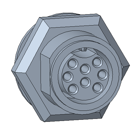
In the product manual or the physical product, users can find two ports as shown in the figure below. One is a 2PIN port, used for the power supply of the user device; the other is an 8PIN port, which includes designated remote control PINs, serial communication PINs, and CAN communication PINs.


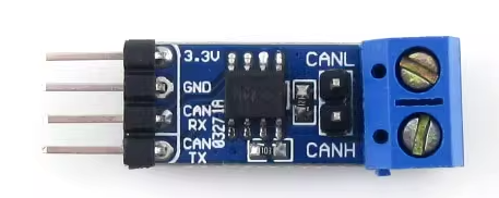
In the product's shipping package, you can find a serial port module identical to the one in the picture. This module is provided by the official, which helps users to get started with serial communication connection quickly.

Please note, users need to prepare a micro USB to typeA USB cable.
The serial port module provided by the official has the following features:
- Using the original Silicon Labs' CP210x USB bridge chip
- TX and RX come with dual-buffer chips, with a maximum drive current up to 20mA, and short-circuit protection support
- TX and RX ports can be freely interchanged, switchable with jumper caps
- Equipped with a 3.3V regulator chip, providing a maximum output current of 470mA
- With USB port 500mA over-current protection, it can effectively protect the computer's USB port
Of course, users can also use their own serial port module, but they need to pay attention to the following two points:
- Note the baud rate 921600 supported by the module
- Note that when the user has replaced the serial port module with a different chip, it is necessary to actively modify the USB ID parameter in the Segway_RMP_Init.sh file. You can use the
lsusbcommand to query specifically.
Users need to actively connect the serial communication cable to achieve hardware communication. Specifically,
- Connect the TX (PIN3) of the 8PIN port and the RX of the serial port module.
- Connect the RX (PIN4) of the 8PIN port and the TX of the serial port module.
- Connect the GND (PIN5) of the 8PIN port and the GND of the serial port module.
Users can verify the connection by using a serial port software or the cat command on the device file. After setting the baud rate to 921600, if data is continuously acquired, the connection is considered successful.
The official does not provide a CAN transceiver module for users. Users need to purchase or design one according to their own products. When choosing a CAN transceiver, users need to ensure that the baud rate supports 500kHz or 1MHz, as different RMP products use different baud rates. The official recommends general-purpose chips such as TCAN1042DRQ1 (the model used by RMP products) and SN65HVD230, among others.
Users need to actively connect the CAN communication cable to achieve hardware communication. Specifically,
- Connect the CANH (PIN1) of the 8PIN port and the CANH of the user's CAN transceiver.
- Connect the CANL (PIN2) of the 8PIN port and the CANL of the user's CAN transceiver.
- Connect the GND (PIN5) of the 8PIN port and the GND of the serial port module. (The connection of GND is optional for users to decide, the official only recommends connecting.)
You can validate the connection either by using a professional CAN inspection device or by actively obtaining CAN device data through the user's device.