Signal Sampling

VHS FM RF / Baseband Composite PAL / 4fsc YUV Decoded Picture
FM RF Archival is a simple preservation scheme to interface with & capture from various analogue media formats on celluloid (magnetic tape) or optical (pitted) substrate recording mediums and preserve them in the digital PCM sampled domain just like standard audio file archives.
Source Media Reading --> FM Waveform/Signals on test points --> PCM Sampling (computer) --> FLAC Lossless compression (40-70%)
Software Decoding --> Baseband Composite (combined) or S-Video (Y/C separated) on file --> Chroma-Decoding (comb-filtering) --> YUV Sampling (digital video files)
Unlike legacy sampling of baseband video at 4fsc (14.3Mhz NTSC & 17.9Mhz PAL) FM RF Archival is normally sampling at 20/40msps or 10~20MHz bandwidth, but unlike the 28.6MSPS & 38.5MSPS rates of 4fsc, sampled signals can be filtered down to as low as 16MSPS for VHS/Betamax/EIAJ/Video8 at 6~8-bits allowing for vastly smaller source signal archives.

Digital PCM or pulse code modulated sampling is a simple concept, your taking wave of voltage information and giving it a high/low value so a 1 or 0 to map the signal into a waveform, higher the sampling more accurate the wave is to a point of 1:1 digital replica.
Detail level per each simple is defined by bit depth so 8-bit means 256 values of information per each sample thinkable in terms of steps of detail and 10-bit means 1024 values and 12-bits is 4096 values.
Bandwidth or sampling speed the amount of information an ADC can accept and convert to useful information is defined by sample rate in SPS or MSPS normally samples per second and million samples per second respectively, 28/54msps are popular due to the 4fsc sampling standard in video world for example, these are typically using 10-bit chips or 12-bit chips despite the signals rarely going over the 8-bit threshold.
Below is the Munday Demo Tape Google Drive / Internet Archive loaded into an audio DAW OcentAudio.
Highlighted is a "frame" of signal information made by 2 separate fields:

Highlighted is a "line" of signal information:

With cutting it down to just 2 fields, inside the DAW you can decode a single frame of information from the exported FLAC file:

1mhz = 2msps of minimum sampling so a 2:1 ratio
Less is worse, more is better, too much is a fixable issue in post.
The best layman's example of this is HiFi 20hz to 20khz (Witch is around the average human hearing range) CD audio is digital 44.1khz just over 2:1 sampling, so 48khz covers the entire range of human speech, ware as 192khz would cover a large array of multiple sound information points like a orchestra, detail and range are both relative to scale of information, such as different sound waves and different colours.
- kHz is 1000hz
- mHz is a million Hz
- MSPS is a million samples per second
This is just the practice of capturing far more information than the potential of the source information, this just wastes space in simple terms and is always preferable.
This is where signal information is lost due to lack of range of signals being captured, this can degrade quality or entirely break the source of what's being captured.
This is where redundant signal information is reduced, typically with an low or high pass filter so signals below or above the range of what's wanted is removed, thus decreasing the space yet also the compression efficiency.
Four times the frequency of SC (sub-carrier)
The digital sampling rate of a composite baseband video signal with respect to the sub-carrier frequency of an NTSC or PAL analogue video signal.
The acquisition sampling rate (initial ADC stage) however varies normally 28.6MSPS to 54MSPS in range, so if you have ever wondered why there is 14.3Mhz/28.6MSPS & 17.7MHz/35.4MSPS rates on for key example the CX Cards, but it's due to this acquisition rate of the initial analog to digital side.

FPS: 29.97
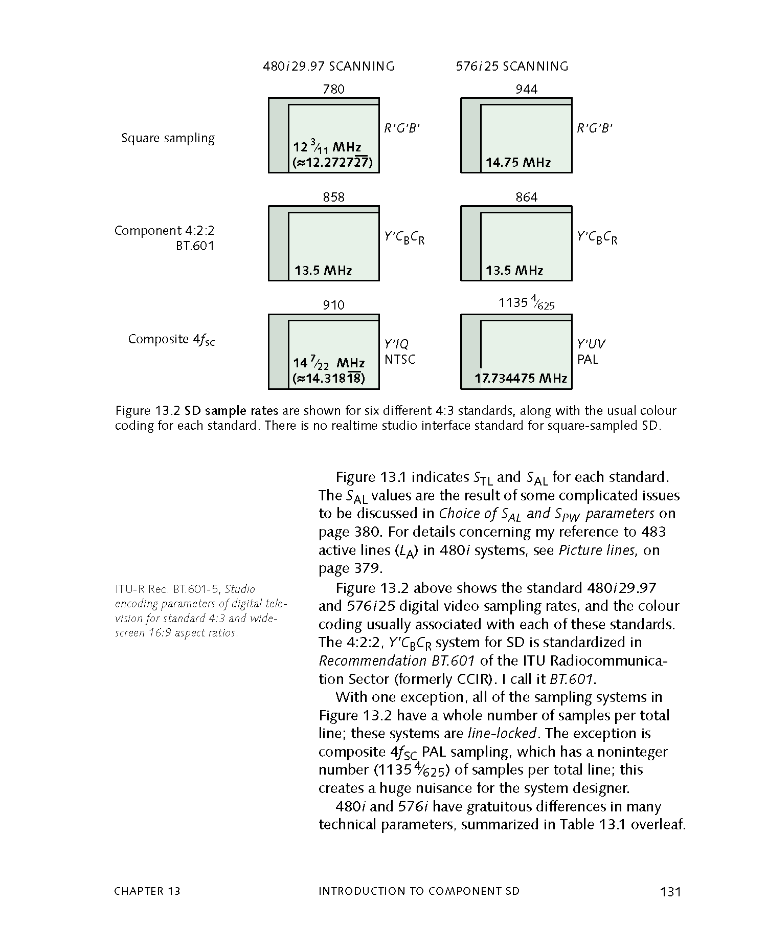
14.31818182 MHz (4x 3.579545455 Mhz)
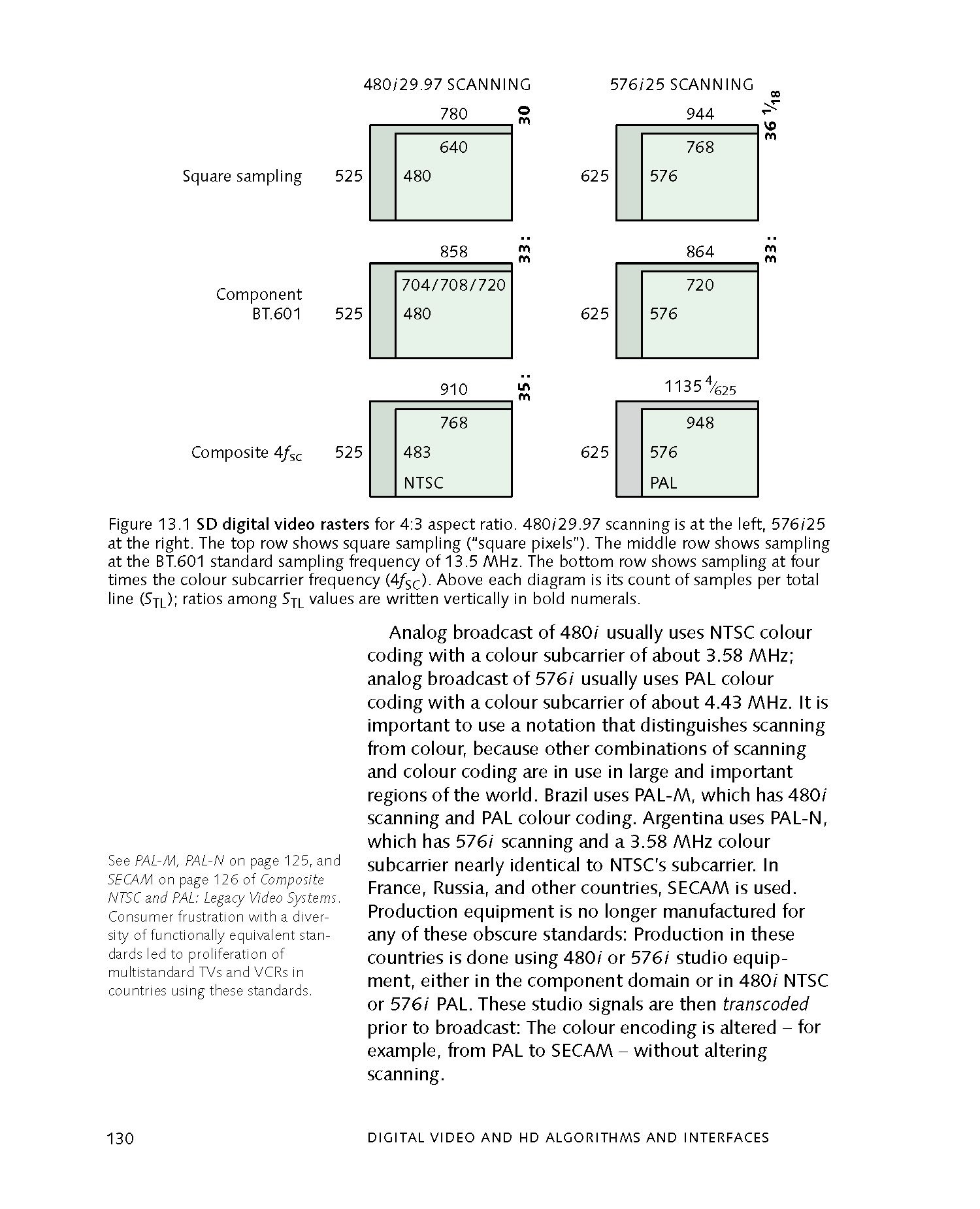
Full Signal Frame: 910x525
Active Picture Area: 720x486 & 720x480
IMX Style Resolution: 720x512 (VBI space preserved, in frame)

FPS: 25
17.734475 MHz (4x 4.43361875 Mhz)
Full Signal Frame: 1135x625
Active Picture Area: 720x576
IMX Style Resolution: 720x608 (VBI space preserved, in frame)
NTSC: 4/times line period ≈ 14.31818 MHz × 63.556 µs ≈ 910 samples/line.
PAL: 17.734476 MHz × 64 µs ≈ 1135 samples/line (1135 + fraction "half line", handled in practice).
Active lines (visible picture):
NTSC: ~480–486 (from 525 total lines, minus vertical blanking).
PAL: 576 (from 625 total lines).
This yields full-frame sampled resolutions like:
NTSC: 910 × 525 (or 910 × 486 active).
PAL: 1135 × 625 (or ~1135 × 576 active).
Decode outputs: 760x488 and 928x576 effectively a power of 2/16 padding, as you can't have fractional pixels for the half-lines of sampling into the pixel domain square or non-square.
Example for NTSC active horizontal scan time / total horizontal scan time * total TBC horizontal width = 52.8(5) / 63.(5) * 910 = 756.79(54), or 757 since you can't have fractional pixels. Add a pixel to make it a multiple of two and avoid those potential issues, add two more to have a single-pixel buffer on each end, and voila: 760. Similarly, for vertical resolution, take the 486 visual scanlines and add two to get the same one-pixel buffer: 488.
928x576 avoids re-scaling the almost-4fsc sample rate that decode uses internally for PAL .tbc storage where each line is 1135 samples long (and 52us out of 64us is active - which would be 922 samples wide - 928 is a convenient, slightly wider than 4:3/16:9 line length)
It's not 4fsc precisely in PAL because decode uses orthogonal sampling with a whole number of samples per line, whereas 4fsc sampling in PAL is 1135 + (4/625) samples per line. (The EBU PAL 4fsc format has 623 lines of 1135 samples per frame plus two lines of 1137 samples per line, one in each field)
NTSC has a whole number of 4fsc cycles per line, so NTSC decode .tbcs are precisely sampled at 4fsc (though I don't think they are phase locked to burst as per the 4fsc digital specs used in broadcast)
928x576 avoids re-scaling the almost-4fsc sample rate that decode uses internally for PAL .tbc storage where each line is 1135 samples long (and 52us out of 64us is active - which would be 922 samples wide - 928 is a convenient, slightly wider than 4:3/16:9 line length)
It's not 4fsc precisely in PAL because decode uses orthogonal sampling with a whole number of samples per line, whereas 4fsc sampling in PAL is 1135 + (4/625) samples per line. (The EBU PAL 4fsc format has 623 lines of 1135 samples per frame plus two lines of 1137 samples per line, one in each field) NTSC has a whole number of 4fsc cycles per line, so NTSC .tbcs are precisely sampled at 4fsc (though I don't think they are phase locked to burst as per the 4fsc digital specs used in broadcast)
Decode's implementation of 4fsc PAL is non-orthogonal, ld-decode was built around keeping things things orthogonal so all the samples align vertically, so went for not-quite-4fsc, without the 4/625 25Hz PAL offset.
A subcarrier is a sideband of a radio frequency carrier wave, which is modulated to send additional information.
Examples include the provision of colour in a black and white television system or the provision of stereo in a monophonic radio broadcast. There is no physical difference between a carrier and a subcarrier; the "sub" implies that it has been derived from a carrier, which has been amplitude modulated by a steady signal and has a constant frequency relation to it.
In simple terms, let's say you have a 5mhz signal, inside this you have audio at 1.2mhz for left and 1.8mhz for right 2.2mhz has a timecode signal and 4.5mhz has the video signal all these signals are modulated
Some good real world examples are the HiFi carrier positions on common videotape formats.
Left 1.3Mhz / Right 1.7mhz
Left 1.5Mhz / Right 1.7Mhz
Left is 1.38Mhz A head & 1.53Mhz B head
Right is 1.68Mhz A head & 1.83Mhz B head
Exurbs From Digital Video and HD Algorithms and Interfaces 2nd Edition (By Charles Poynton 2012-02-07)
Pages 162 to 180
The following pages give a clear explanation of what 4fsc, S-Video, and Chroma Sampling are, witch are the core surface concepts to understand the processing chain of software tape decoding and how analogue is presented in the digital domain.
Four times the frequency of subcarrier, this is normally based off the composite signal standard for PAL/NTSC.
The 4fsc frequency sample rate is typically:
14.3 MHz (28.6 MSPS) in NTSC.
17.7 MHz (35.4 MSPS) in PAL.
In simple terms the same system used for D2/D3 tape.
Page 171
Page 172
Stephen_Neal — 09/05/2025
A question asked a lot in the digital user meets analog world is why 4:4:4 10-bit is not used for analog video sampling, this section aims to clear this up in practical and conceptual terms.
Nyquist is Nyquist - pixel peeping on a PC will always be in the RGB domain pretty much - so you are always doing a 4:2:2/4:4:4 to RGB conversion to pixel peep on a PC.
You will see a difference in many cases between 4:2:2 and 4:4:4 in this domain (because you can have chroma differences at pixel not pixel-pair resolution)
but those differences don't mean there is source information there. It is often just more noise. However much, intuitively, it sounds that sampling a 300kHz bandwidth (VHS Chroma) signal 20 times more than you need to rather than 10 times more than you need to will improve things - it won't.
Once you're past Nyquist for your signal, you're capturing it all.
As long as you stay within the same sampling structure after this - you don't get loss from conversion. That's why the broadcast and post industry is standardised on 4:2:2 to avoid conversions between 4:2:0, 4:1:1, 4:4:4 etc.
@Marshalleq
I get what you're saying but I don't think that's how it works.
Chroma subsampling is not pre-defined holes that always know where to find themselves in subsequent conversions.
I did some testing and could clearly see loss over generations. It' s particularly bad in low resolution as there's less detail to begin with.
04:46 AM
Nyquist is Nyquist though - with 4:2:2 sampling of VHS chroma you are capturing a 0.3MHz bandwidth signal in a channel designed for 2.75MHz bandwidth signal. That's already massive overkill of the order of 10x more than you need. You are oversampling to a ridiculous degree with 4:2:2 capture of VHS. With 4:4:4 it's just pointless. You're just more accurately capturing noise.
You can fully capture a 2MHz luminance, 0.3MHz chrominance bandwidth VHS signal with 1.4:0.22:0.22 sampling... 2:0.5:0.5 (i.e. 2.875MHz luminance, 687.5kHz chroma bandwidth) would be overkill and accurately capture the source.
VHS for example can be stored in 320x576 25i 4:1:1 YUV with FFV1 at under 20mbps lossless in terms of luma/chroma, but if this file was to be used in editing it would run into the conversion problems
- FAQ - Frequently Asked Questions
- Diagram Breakdowns
- Visual-Comparisons
- VCR Reports / RF Tap Examples
- Download & Contribute Data
- Speed Testing
- Capture Setup Guide
- MISRC
- CX Cards & CXADC
- CX Cards - Clockgen Mod
- DdD - Domesday Duplicator
- RTL-SDR
- Hardware Installation Guide
- Finding RF Tap Locations
- Amplifier Setup Guide
- The Tap List Example VCR's
- Visual VBI Data Guide
- Closed Captioning
- Teletext
- WSS Wide - Screen Signalling
- VITC Timecode
- VITS Signals
- XDS Data (PBS)
- Video ID IEC 61880
- Auto Audio Align
- Vapoursynth TBC Median Stacking Guide
- Ruxpin-Decode & TV Teddy Tapes
- Tony's GNU Radio For Dummies Guide
- Tony's GNU Radio Scripts
- DomesDay Duplicator Utilities
- ld-decode Utilities