2. Components and Technical Specifications
The helium level meter is designed to withstand the usual environmental conditions. It has a typical battery life of 4 weeks (depending on the measurement interval). The technical drawings are shown in the appendix.
Table 1: Specifications of the helium level meter.
| Property | Value |
|---|---|
| Water tightness | IP62 |
| Temperatures | -10°C – 40°C |
| Battery capacity | 9000 mAh (7.2 V) |
| Battery life | typ. 4 weeks (depending on measuring parameters) |
| Frequency band | ISM 2.4 GHz |
| Transmit power output | 1 mW – 3 mW |
| Range of wireless connection | up to 30 m (indoor), up to 90 m (outdoor line-of-sight) |
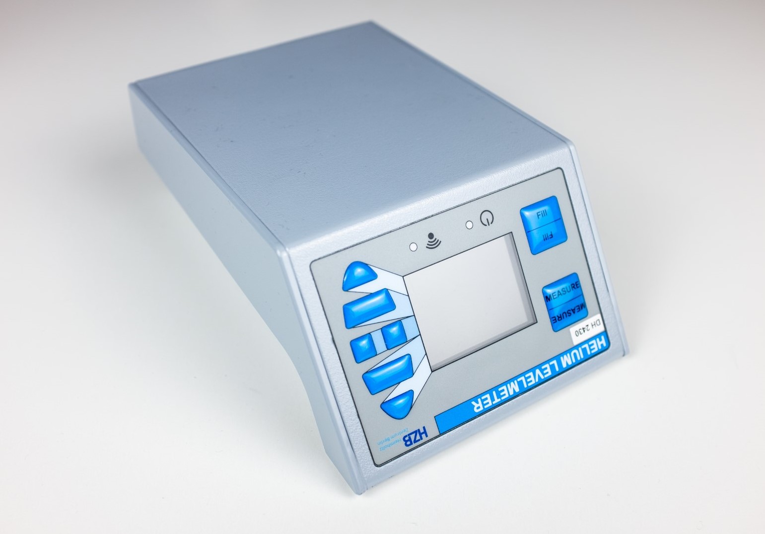
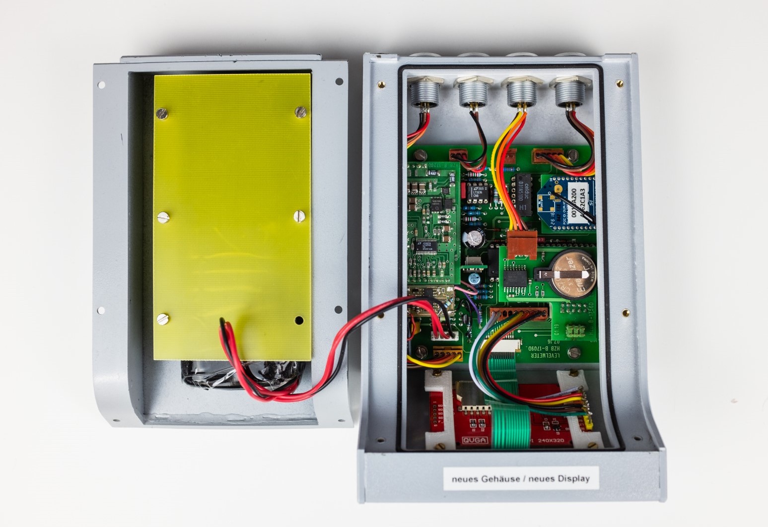
Figure 1: The helium level meter developed at HZB – exterior and interior view.
The housing is sealed against rain. The level meter can be easily mounted to helium vessels using a separate holder. The holder is permanently attached to the vessel.
The level meter is operated via eight buttons and a color display with background lighting. Conventional buttons have the advantage of being able to be operated with gloves. There are two hidden buttons above the display which enable special functions. The layout of the front is designed the way that the device also can be used upside down.
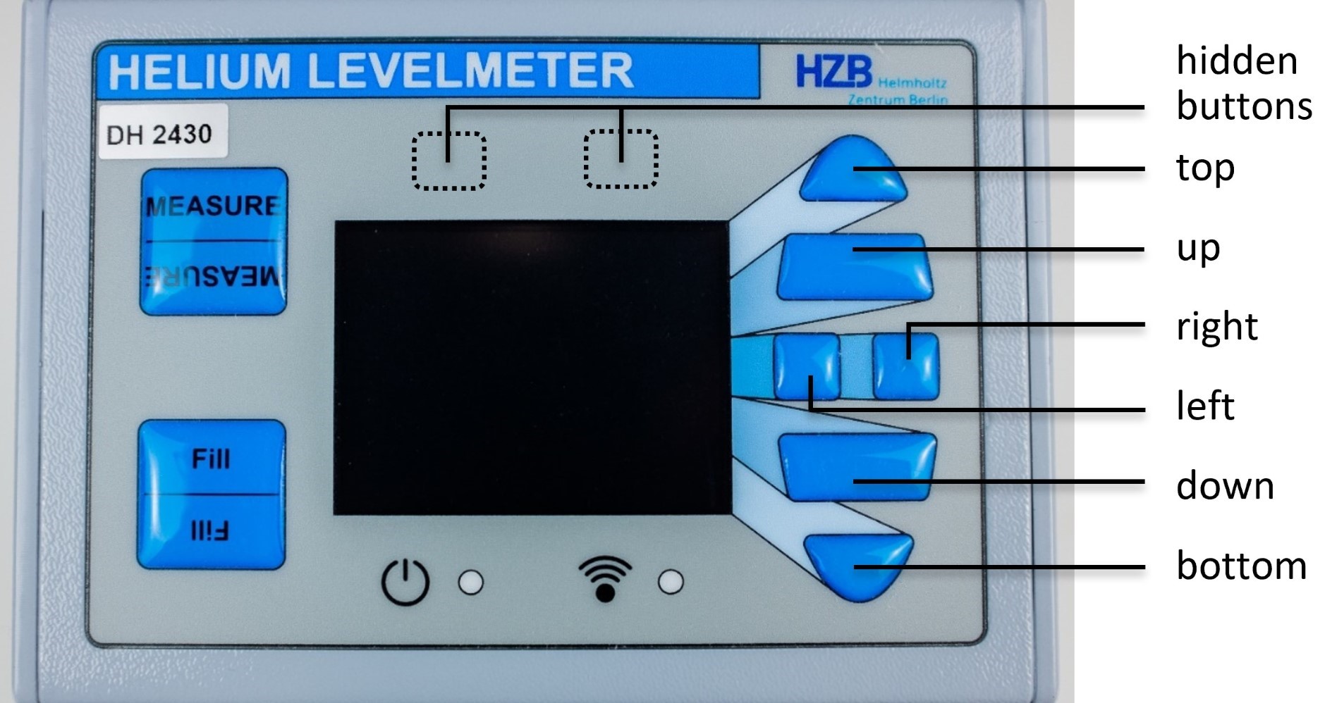
Figure 2: Front side of the helium level meter with labeled buttons.
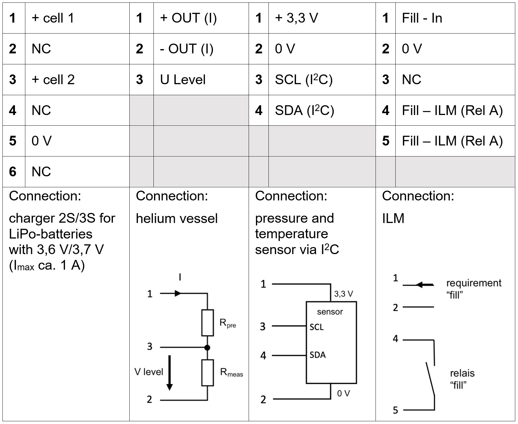
The helium level meter provides four connectors (manufacturer: LEMO) at the backside with different numbers of pins. There is a 6-pin port for charging the battery, a 3-pin port for the connection to the helium probe, a 4-pin port for the connection to the pressure and temperature sensor and a 5-pin port for the usage of the automated filling procedure (Autofill). The manufacturer’s numbers of the utilized receptables and plugs are summarized in table 2 while the assignment of the pins is shown in table 3.
Table 2: Description of the four connectors at the backside of the helium level meter.
| Function | Battery charge | Level probe | Pressure/temperature | Autofill |
|---|---|---|---|---|
| Number of pins | 6 | 3 | 4 | 5 |
| Receptable | HGP.1S.306.CLLP | HGP.1S.303.CLLP | HGP.1S.304.CLLP | HGP.1S.305.CLLP |
| Plug | FFP.1S.306.CLAC62 | FFP.1S.303.CLAC62 | FFP.1S.304.CLAC62 | FFP.1S.305.CLAC62 |
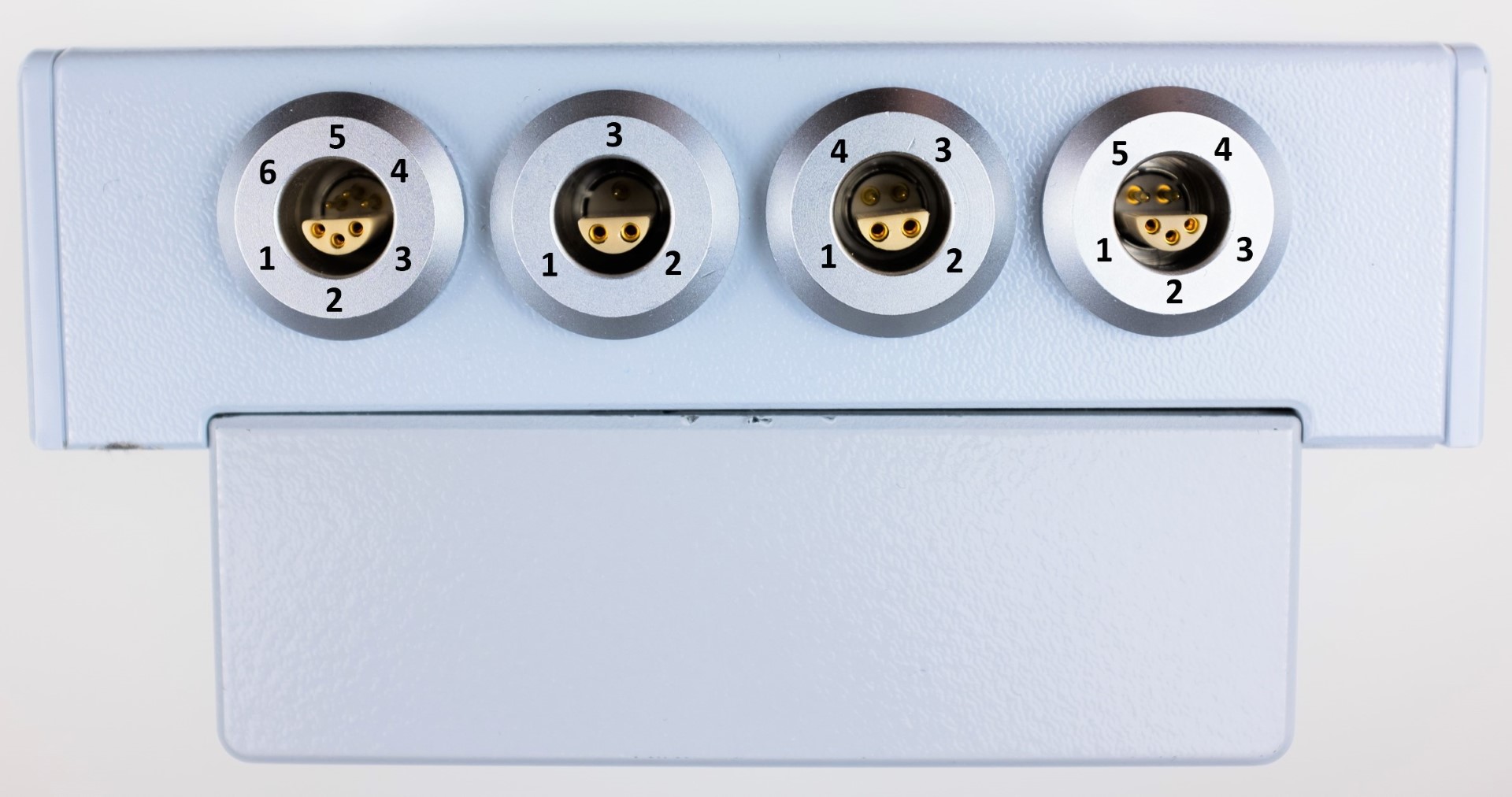
Figure 3: View on the four connectors of the helium level meter with numbered pins.
Table 3: Assignment of the pins of the ports at the backside of the helium level meter.
The device has an internal battery pack with a capacity of 9000 mAh at a nominal voltage of 7.2 V. It consists of four Li-Ion cells of the type 26650 with a single capacity of 4500 mAh at a voltage of 3.6 V. These cells are connected in a 2s2p scheme (two serial two parallel) as shown in figure 4. The total voltage of the battery pack can be measured via the supply wires which connect the parallel circuits. Moreover, the single cell voltages can be tapped via an additional wire between the cells of the parallel circuits. This also enables balancing of the cells during charging. A protective circuit protects the cells from overcharge, deep discharge and overcurrent. In addition, two thermal fuses (72°C) protect the cells from overheating. The four-pin connector is used for charging the battery while the three-pin diagnosis connector is meant for monitoring the cell voltages directly, i.e. independent from the protective circuit. The battery is charged using an appropriate charger which also provides for a balancing of the cells. It also controls the charging current in dependence of the charge status and turns off when the battery is full. At maximum, a charging current of 4 A could be used but 1 A is recommended as normal charging current which needs 9 hours to completely charge the battery.
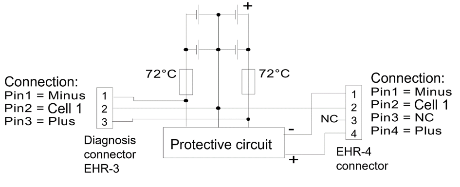
Figure 4: Battery circuit including four cells, two thermal fuses at 72°C, a protective circuit, a diagnosis connector and the charging connector. The charging connector is inside the level meter between PCB and battery pack.
In case that the battery is deep discharged and normal charging with the appropriate charger does not work, please see chapter 6 - deep discharge.
The level meter can be part of the Helium Management System. In this case the level meter transmits its readings wirelessly via the HMS base stations (coordinators) to the HMS server software. For the radio connection modules with the brand name Digi XBee from Digi International are used. The modules operate within the ISM 2.4 GHz frequency band with a transmit power output of 3 mW. Their indoor range is up to 30 m and the line-of-sight range up to 90 m. The transmission protocols are shown in the appendix. If there is no HMS installed, the level meter can be used in offline mode and all necessary settings can be set locally.