3. User Interface
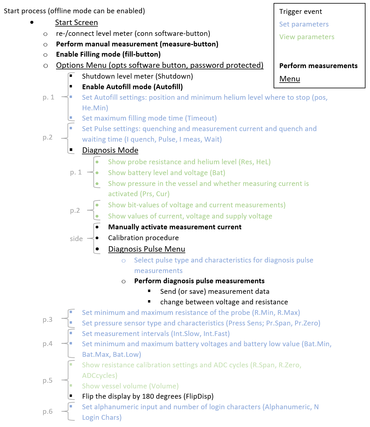
The structure of the operating system is shown in the following list. The explanations in this chapter follow this order.
The start process of the helium level meter is illustrated by figure 5. In all following interface descriptions, it is oriented the way that the navigation buttons are on the right side of the display.
The helium level meter is started by pressing the “MEASURE”-Button. At first, it runs a system test to check whether the internal timer (including the temperature sensor) and the external pressure sensor are connected. These sensors will only work if they are already connected during this system test. Afterwards, it automatically tries to establish a connection to HMS base station and executes the first measurement of the helium level after typing in the identification code of the vessel. This is necessary to identify the vessel in the database when the device is operated as part of the Helium Management System. The start process ends when the start screen is shown.
There are two hidden buttons above the display (see fig. 2). By pressing them simultaneously during the network establishment phase at the beginning, the offline mode is activated. This means that no data connection is established and the device remains without network connection as the device runs. Furthermore, the measurement values used most recently which are stored in the EEPROM, will be used for all subsequent measurements. They nonetheless can be changed in the options.
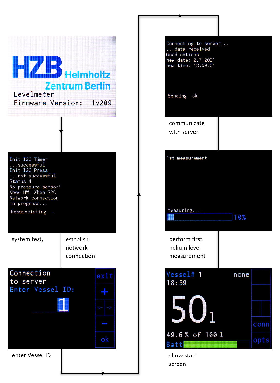
Figure 5: Start process of the helium level meter.
On the start screen all important information is displayed as shown in figure 6. This includes the vessel ID, the pressure inside the vessel, the system time, the filling level in liter and percent, the total vessel volume and the battery level of the helium level meter. The position for the Autofill and Filling Mode is displayed as well. In addition, two buttons are available with the functions “conn” (connection) and “opts” (options).
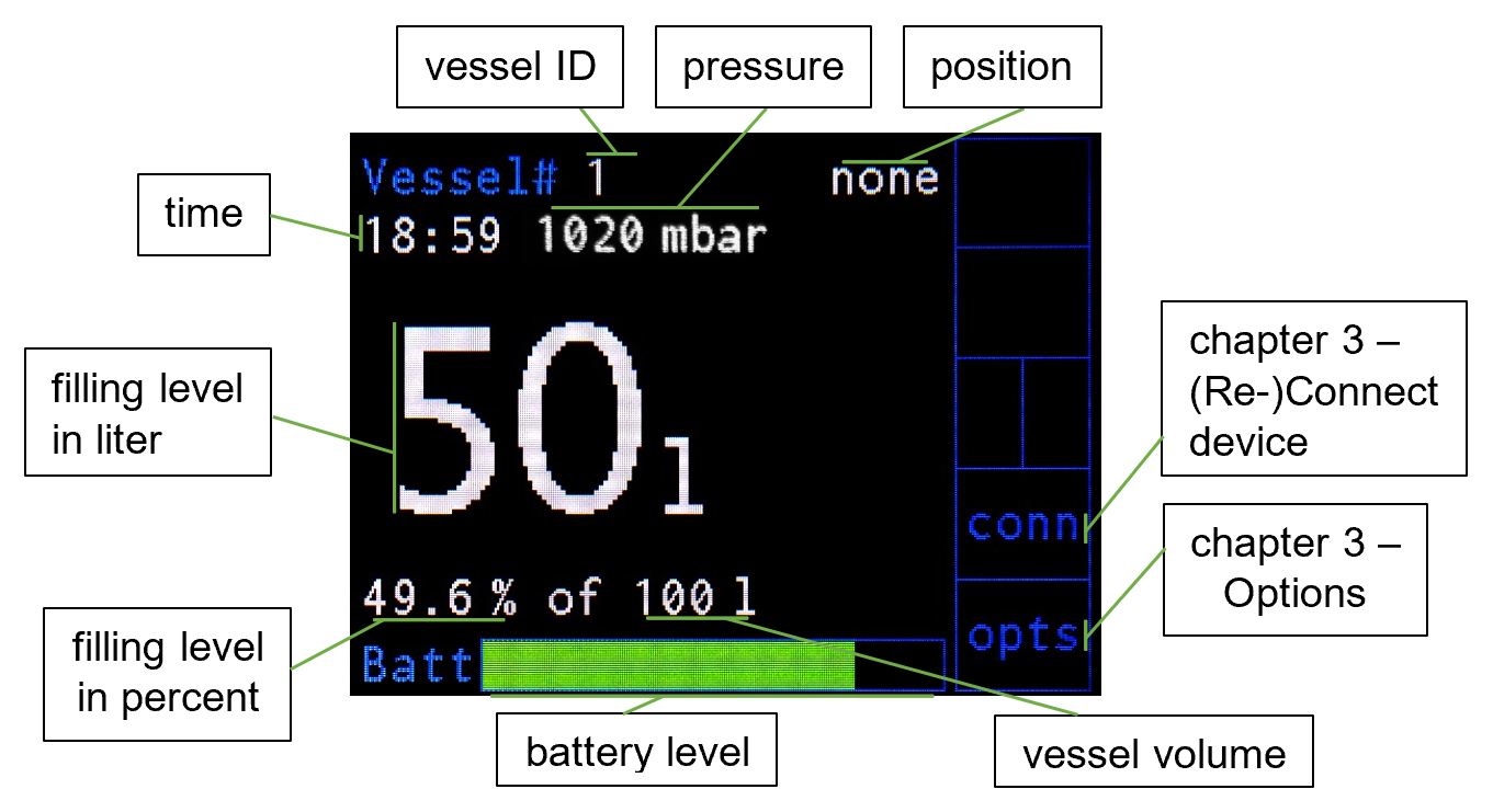
Figure 6: Start screen of the helium level meter with labels of the shown elements.
When the device shows the start screen you can
- manually perform an additional measurement by pressing the “MEASURE”-button (see chapter 3 - Manual Measurement)
- start the filling mode by pressing the “Fill”-button. In this mode the device is assigned the cryostat to be filled and measures the helium level in shorter intervals (see chapter 3 - Filling Mode)
- manually reconnect the device by pressing the “down”-button next to “conn” (see chapter 3 - (Re-)Connect Device)
- enter the options by pressing the “bottom”-button next to “opts” (see chapter 3 - Options)
Already during the start process the helium level meter undergoes the network establishment procedure. If there is the wish to connect or reconnect the helium level meter to the network afterwards, this can be achieved by pressing the “down”-button next to “conn” on the start screen. This starts the network establishment procedure.
The helium level meter automatically performs periodic measurements to monitor the level. If wished, additional manual measurements can be taken by pressing the “Measure”-button.
If a vessel is used for refilling a cryostat, the filling mode should be activated when the device is used within a network. This mode can be started by pressing the “Fill”-button. After entering the position which e.g. is the cryostat name or its room number, periodic measurements are performed in shorter intervals than in the normal state. Furthermore, the used helium is assigned to the give position inside the HMS.
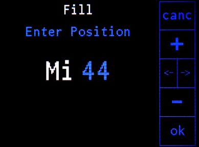
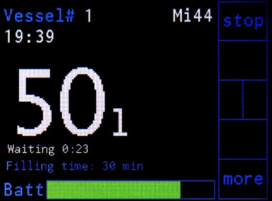
Figure 7: Left: starting window of the filling mode and entering as position “Mi 44”; right: during the filling process with 23 s until the next measurement of the level and 30 min remaining time in the filling mode.
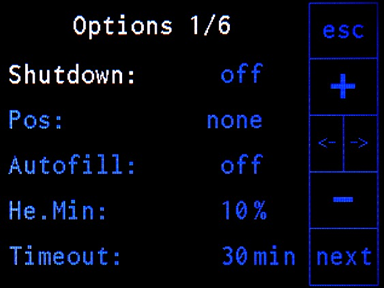
The options menu is protected by a password which is defined in the HMS server program. The initial password is 001. Figure 8 shows the pages of the options menu.
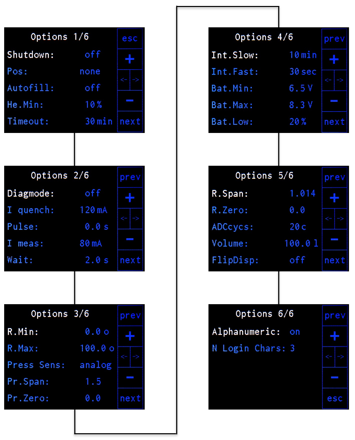
Figure 8: Overview of the options menu with its 6 pages of settings.
The explanations of the different settings are given in the following tables
| Setting | Description |
|---|---|
| Shutdown | Switch off the level meter. |
| Pos | Choose a position for the autofill procedure out of the predefined positions transmitted from the server during the initialization (see section Autofill). |
| Autofill | Enable / disable the autofill procedure. |
| He.Min | Minimum allowed helium level for the autofill procedure, autofill will stop when the measured level falls below this value. |
| Timeout | Maximum time of the filling procedure (not active in autofill mode!). |
| Setting | Description |
|---|---|
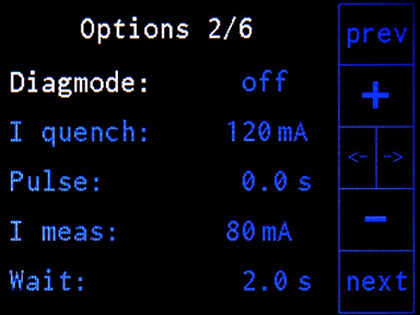
| Diagmode | Sub menu which includes two more pages for analyzing the helium probe (explained in more detail after the explanation of page 5). |
| I quench | Current used for heating the helium probe (superconducting wire) before measuring the helium level. |
| Pulse | Duration of quench current (I quench) applied to the helium probe. This correlates with the red colored part of the pulse diagram of the Diagmode (see the section Diagnosis Mode). |
| I meas | Current applied to the helium probe for measuring the resistance after the quenching. |
| Wait | Waiting time after the application of the quench current and before the measurement of the resistance after the current is changed from quench current (I quench) to measurement current (I meas). This correlates with the blue colored part of the pulse diagram of the Diagmode (see the section Diagnosis Mode). |
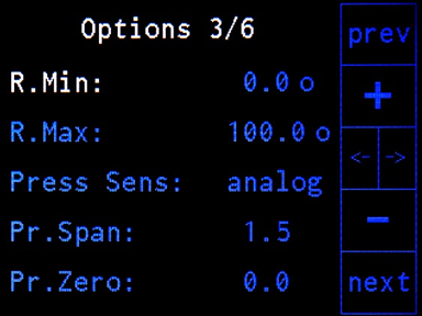
| Setting | Description |
|---|---|
| R.Min | Minimum resistance of the helium probe which corresponds to a helium level of 100% (full vessel). |
| R.Max | Maximum resistance of the helium probe which corresponds to a helium level of 0% (empty vessel). |
| Press Sens | Choose pressure sensor. Options: off, I2C, analog. Warning! The type of the pressure sensor is defined at delivery. The electronics of the level meter have to be adapted if the type of sensor is changed. |
| (Pr.Span) | (Only shown for analog pressure sensor) span value for corrections with analog pressure sensor |
| (Pr.Zero) | (Only shown for analog pressure sensor) zero offset value for corrections with analog pressure sensor |
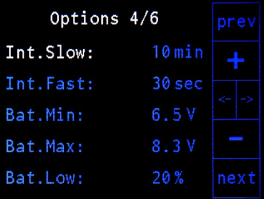
| Setting | Description |
|---|---|
| Int.Slow | Slow measurement rate in normal mode |
| Int.Fast | Fast measurement rate in filling mode |
| Bat.Min | Minimum battery voltage, level meter will shut down when the battery voltage drops below this value. |
| Bat.Max | Maximum battery voltage |
| Bat.Low | Level (in percent) for battery alarm |
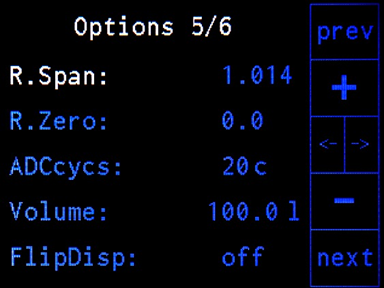
| Setting | Description |
|---|---|
| R.Span | Calibration value “span” for the more accurate measurement of the resistance (see Calibration Procedure of the Resistance Measurement) |
| R.Zero | Calibration value “zero” for the more accurate measurement of the resistance (see Calibration Procedure of the Resistance Measurement) |
| ADCcycs | Number of integration cycles for the AD converter (40 cycles give reasonable results) |
| Volume | Volume of the vessel in liter which corresponds to a level of 100% (full vessel). |
| FlipDisp | By activation the content on the display can be rotated by 180 degrees (see the section Rotate Display). |
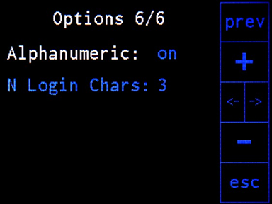
| Setting | Description |
|---|---|
| Alphanumeric | Enable or disable alphanumeric input for the vessel ID (0-9 & A-Z or only 0-9). |
| N Login Chars | Set the ID length between 3 and 6 characters. |
The helium level meter can be shut down in two ways. The first possibility is to enter the options page 1 and enter „Shutdown“. The second one uses the buttons „left“ or „right“. This starts the same procedure as using the „Shutdown“ in the options menu. The third way is only foreseen for a malfunction of the device. By pressing the two hidden buttons above the display (see figure 2 in Display and Buttons) simultaneously for some seconds the device can be shut down directly (see chapter 4 – Hidden Functions).
The Autofill mode enables for automated filling of cryostats using appropriate additional equipment. This includes the Helium Autofill 2 device which serves as control unit for the automated filling and a suitable siphon with three electronically controllable valves. For more detailed information on this, please see the corresponding Helium Autofill 2 manual from Helmholtz-Zentrum Berlin.
By activating the Autofill mode on page 1 of the options, the level meter can be triggered by an incoming start signal of the Helium Autofill 2 device to enter the filling mode and to perform level measurements of the liquid helium vessel with higher frequency. During the automated filling the helium level meter only serves as a control instance which checks whether the filling level of the helium vessel is below or above a threshold value which is set also in the options on page 1. When the filling level falls below the threshold value, the level meter switches its output at the Autofill connector from 1 to 0 and thus informs the Helium Autofill 2 device that it should end the filling process.
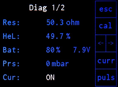
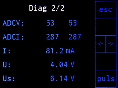
Figure 9: Overview of the pages of the diagnosis mode which is accessible via page 2 of the options. The current accessible via the button at the side is enabled.
The calibration procedure of the resistance measurement (see Calibration Procedure of the Resistance Measurement) can be accessed via this menu. It also enables the diagnosis of the resistance and battery voltage measurement and provides a detailed diagnostics of the helium probe via a new menu (see Diagnosis Pulse Menu) which can be entered by pressing the “puls”-button.
In addition to the functions accessed by the “cal”- and the “puls”-button which are explained below in more detail, there is another function accessible by pressing the “curr”-button. By doing so, the measurement current (I meas on options p. 2) is applied to the helium probe without following the normal measuring process including the quenching of the probe. This function is intended for the simple debugging of the resistance measurement using the values displayed on page 2 of the diagnosis mode. The current can be switched off by pressing the “curr”-button again.
| Setting | Description |
|---|---|
| Res | Measured resistance of the helium level meter when the current is turned on. The current can be switched on and off by pressing the “curr”-button. |
| HeL | Helium level in percent corresponding to the measured resistance of the helium probe when the current is turned on. |
| Bat | Battery status: battery level and voltage |
| Prs | Measured pressure inside the vessel when a pressure sensor is connected |
| Cur | States if the manual measuring current is turned on which can be switched by pressing the “curr”-button. |
| Setting | Description |
|---|---|
| ADCV | Bit-value of the voltage measurement of the sensor (max. 1024) |
| ADCI | Bit-value of the current measurement (max. 1024) |
| I | Measured current |
| U | Measured voltage at the active part of the helium level probe |
| Us | Supply voltage |
The internal resistances of the liquid helium level meter should be calibrated to achieve higher precision. For this purpose, a calibration is implemented which is accessible via the diagnosis mode.
By pressing the “cal”-button in the diagnosis mode a calibration procedure is started. At first, the user is asked if the previous calibrated values (R.Span and R.Zero) shall be set to default values. After confirming, the level meter asks for connecting two resistors close to the R.min and R.max values (options page 3). A set of suitable resistors can be provided by the manufacturer. Alternatively, a resistance decade can be connected to the level meter for the calibration procedure. The results of the calibration will be accessible via the values R.Span and R.Zero (options page 5).
This menu is entered from the Diagmode menu by pressing the “puls”-button. It enables a comprehensive characterization of the liquid helium probe by offering three different pulse types which can be applied to it. For more information on this please see chapter 5 Characterize the Helium Probe of a Vessel.
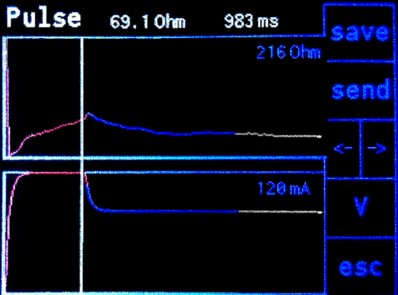
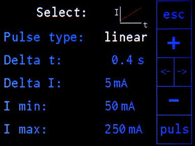
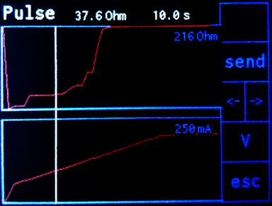
The „normal“ pulse uses a quenching current for a duration given by „Pulse“ and then applies the measurement current “I meas”. “normal” refers to the fact that this mode is used by the level meter for regular measurements. The „constant“ pulse only applies one constant current to the probe. The third option „linear“ pulse applies different currents to the probe which lie on a straight line. Therefore, the minimum and maximum current are given as well as the step size and the time per step. The three pulse types are explained in the following with figures and tables.
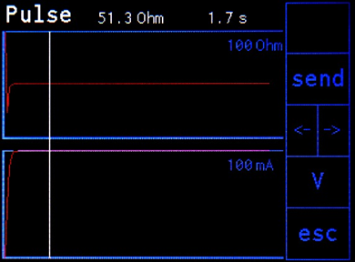
After the measurement, there are some options, accessible via the side. The cursor line can be moved with the arrow buttons and the corresponding values of the upper diagram are shown above it. In the normal mode, the values set can also be saved which means that they would be used in the regular measurements of the level meter (filling mode etc.). The measurement can also be sent to the HMS via the send button. With “V” or “RES” the upper diagram can be switched between showing voltage and resistance, respectively. With “esc” the measurement can be leaved to return to the diagnosis pulse menu.

| Setting | Description |
|---|---|
| I quench | Set the quenching current to quench the liquid helium probe (current at the red line). |
| Pulse | Define the duration of the quenching current applied to the probe (red part). |
| I meas | Set the measuring current applied to the probe after the quenching current. |
| Wait | Waiting time after the quenching current (blue line) before the level meter would measure the resistance (white line) in regular operation to derive the filling level. |
The “normal” pulse type is used by the level meter for regular measurements. With this pulse type, first, a higher current is used for heating up the helium probe and second, a lower current is used for doing the measurement of the helium level. It offers setting four parameters: The current value at the beginning and its duration, the value of the following lower current and the waiting time before doing the measurement. These sections are also marked above in different colors. The resistance in the measurement section (white line) should be constant to ensure reliable results.
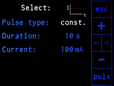
| Setting | Description |
|---|---|
| Duration | Set the length of the current to be applied to the liquid helium probe. |
| Current | Set the current to be applied to the probe. |
| Setting | Description |
|---|---|
| Delta t | Time after doing a new current step before doing the measurement. |
| Delta I | Set the step width of the current measurements. |
| I min | Set the current value where to start with the scan. |
| I max | Set the maximum current value where to end with the scan. |
To adapt the device to the way it is mounted, the content on the display can be rotated by 180 degrees by changing the value of “FlipDisp” on page 5 of the options menu.