4. Operation
This chapter explains how to use the helium level meter and gives an introduction to the operating system. After the explanation of the initial setup of the level meter follows an introduction to the daily operation which covers the mounting on the vessel, the start process and a description of the operating modes. Then, charging, shutting down and hidden functions are explained.
If you are searching for a comprehensive and sorted explanation of the whole operating system, please see chapter 3 - "User Interface".
Two steps have to be executed as an initial setup before the first mounting on a vessel. These include:
- Registration of the level meter in the HMS
- Calibration of the level meter
When using a Helium Management System (HMS), the level meter must be registered to enable communication between the device and the HMS. Therefore, a new level meter entry must be added in the HMS via Settings -> Levelmeter -> -Create new Levelmeter-.
There, the xBee-address of the new level meter must be entered as well as its name and serial number. By choosing “Levelmeter default” in the field of “Level Meter Type”, the default battery values are used for the device.
The internal resistances of the liquid helium level meter should be calibrated to achieve higher precision. After having charged the device, start the level meter by pressing the “MEASURE”-button. After a system test, the identification code of a dummy vessel needs to be typed in. If not available, press the two hidden buttons above the display simultaneously to start the Offline mode. Set the maximum and minimum resistance values in the level meter corresponding to the vessels’ superconducting helium probes which are going to be used (options page 3). Depending on these values the level meter demands certain resistors for doing calibration. The calibration is started via the Diagnosis menu (options p. 2, turn DiagMode on) and press “cal”. During the calibration, connect the demanded resistors to perform a linear calibration of the device in the specified range. If you don’t have the max. and min. resistances of the vessels’ probes, then characterize them first and calibrate the level meter after having obtained these values. The device is delivered pre-calibrated (at 10 Ω and 100 Ω), but new calibration increases the accuracy of the resistance measurements. A set of suitable resistors can be provided by the manufacturer. Alternatively, a resistance decade can be connected to the level meter for the calibration procedure. The results of the calibration will be accessible via the values R.Span and R.Zero (options page 5).
After having done these two steps of the initial setup, the level meter is already ready for use. The daily operation is explained in the following subchapter, covering the mounting, the start process and the operating modes.
As explained in chapter 2 (Components and Technical Specifications) the helium level meter has four ports with different functions which is shown in figure 10.
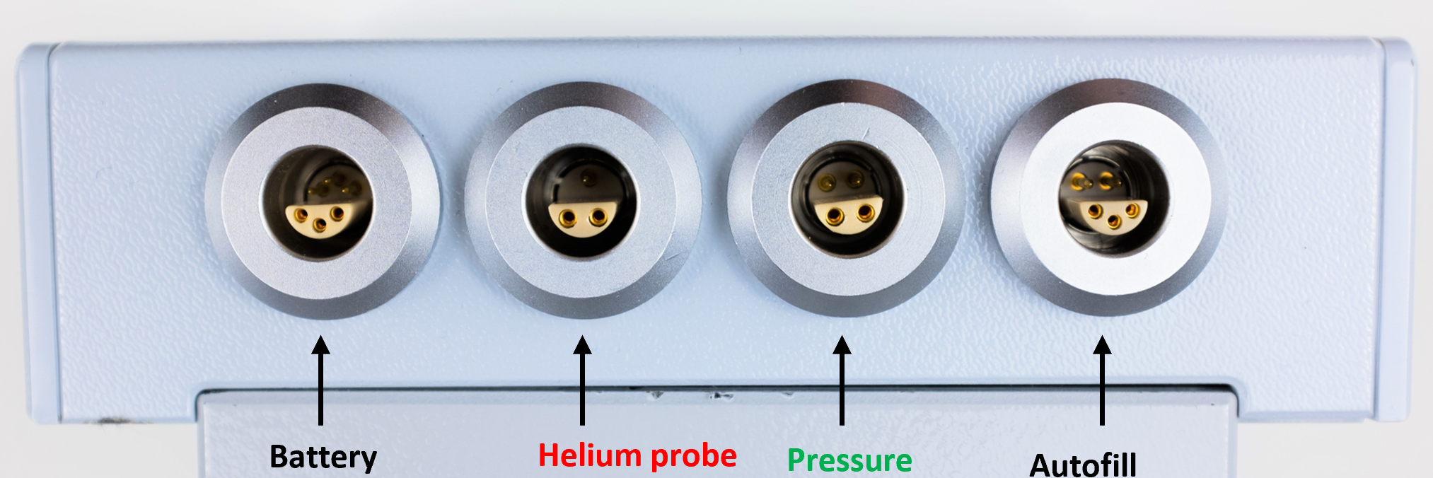
Figure 10: Assignment of the four ports of the helium level meter.
For mounting the level meter on a helium vessel, the helium probe must be plugged into the helium probe port and the pressure sensor if available into the pressure sensor port. The resulting setup is also schematically shown in figure 11.
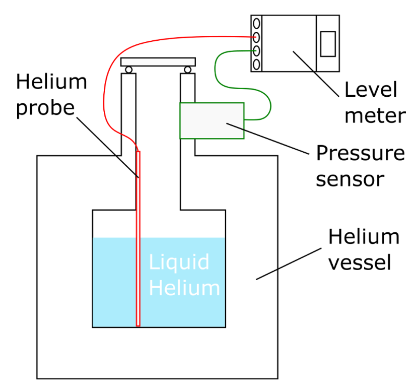
Figure 11: Setup with mounted level meter on helium vessel.
The helium level meter is started by pressing the “MEASURE”-Button. This activates the start process. In all following interface descriptions, it is oriented the way that the navigation buttons are on the right side of the display. At first, the level meter runs a system test to check whether the internal timer (including the temperature sensor) and the external pressure sensor are connected. These sensors will only work if they are already connected during this system test. Afterwards, it automatically tries to establish a connection to HMS base station and executes the first measurement of the helium level after typing in the identification code of the vessel. This is necessary to identify the vessel in the database when the device is operated as part of the Helium Management System. After establishing a connection to the HMS, all available data regarding the specified helium vessel and the level meter are transferred. The start process ends when the start screen is displayed.
On the start screen all important information is displayed. This includes the vessel ID, the pressure inside the vessel, the system time, the filling level in liter and percent, the total vessel volume and the battery level of the helium level meter. The position for the Autofill procedure is displayed as well. In addition, two buttons are available with the functions “conn” (connection) and “opts” (options).
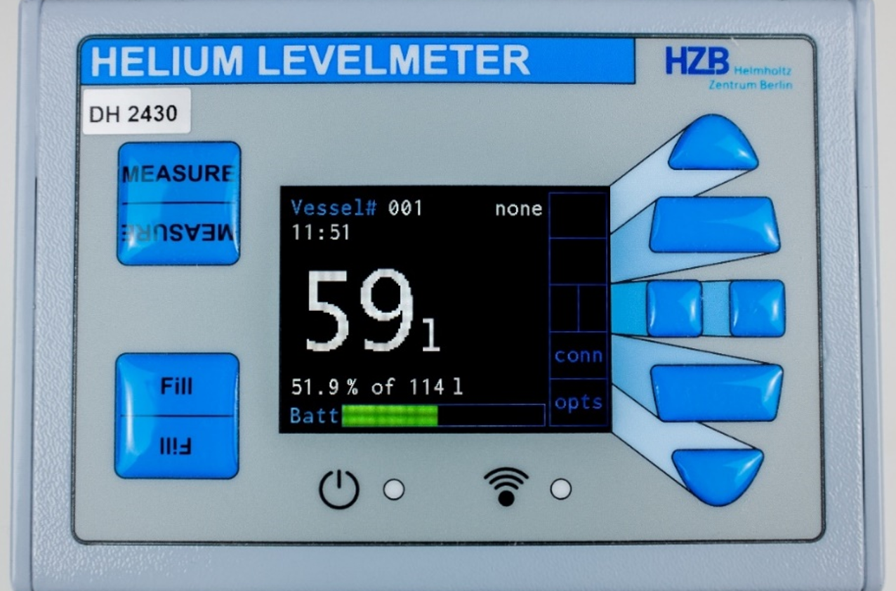
Figure 12: Front of the level meter showing the start screen.
When using the level meter in Offline mode or without an HMS, the values stored in the EEPROM from the most recent measurements will be used. If the values have already been entered before, they should be taken over automatically. Otherwise, if no values have been entered before or need to be changed, enter the options menu by pressing the “bottom”-button next to “opts. The options menu is protected by a password which is defined in the HMS server program. The initial password is 001.
- The helium vessel volume,
- the parameters used for performing the helium level measurements on page 2 of the options: I quench, Pulse, I meas and Wait (quench current, quench current time, measurement current and waiting time). These values are unique for each individual helium probe. If these values are not known, please see chapter 5 "Characterize the Helium Probe of a Vessel" and follow these instructions first.
- The minimum and maximum resistances of the helium probe R.Min and R.Max (p.3) also available by the characterization of the helium probe.
- Press Sens (p.3): enter whether a pressure sensor is used and the type of pressure sensor. When using an analog sensor, further values Pr.Span and Pr.Zero appear below and must be entered. Attention: Changing the pressure sensor type needs a hardware modification of the device! In this case, please contact the manufacturer!
- FlipDisp (p.5): rotate the display content by 180 degrees if necessary.
Now, that the helium level meter is mounted on the vessel and the hardware is set up, the different operating modes are presented in the following subchapter.
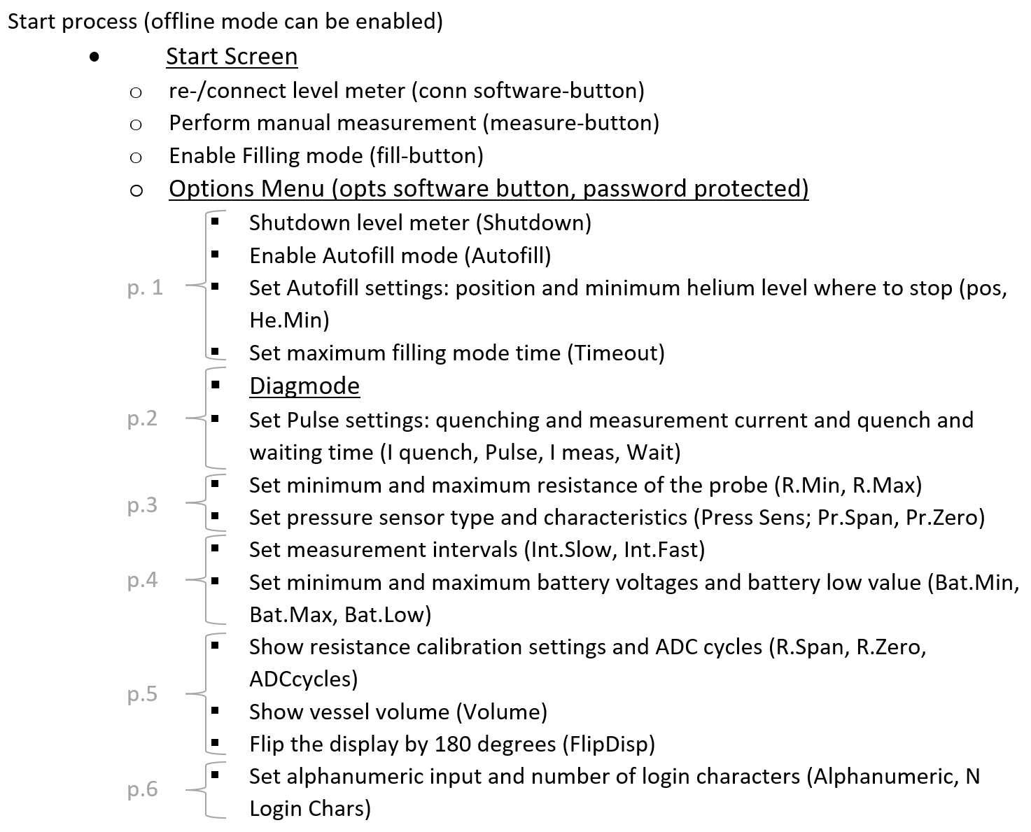
The level meter is designed for different modes of operation: Standby mode, Filling mode, Autofill mode and Diagnosis mode. All these modes require additional information like for example the time interval between measurements or the minimum level where to stop filling in the Autofill mode. Figure 13 provides an overview of the settings and their affiliation to the different modes including an explanation of them. The link between the shown settings and their position in the options menu is given by a list afterwards. These parameters are also transferred from the HMS to the level meter but can be changed as preferred.
In figure 13 the operating modes are shown as being embedded into the operating system, which is colored gray. We already have set the corresponding settings like the pressure sensor type which appear as grey fields.
The central orange area represents the core function of the level meter. The settings shown in the orange fields are necessary to perform helium level measurements and to determine the filling height in percent and liter. As supposed in subchapter “Initial Setup of the Level Meter” the level meter should also already be calibrated (via the Diagnosis mode; orange field in dark blue area). If problems occur regarding the measurement of the level, the parameters in the central orange area must be probably modified. For doing so, please see chapter 5 "Characterize the Helium Probe of a Vessel" and follow these instructions.

Figure 13: Assignment of the helium level meter settings to the different operating modes.
In the subchapter “Daily Operation – Start Process of the Level Meter” the measurement pulse settings (second orange field from top) were transferred from the HMS (or set in Offline mode or without HMS) as well as the minimum and maximum resistances of the probe (third orange field from top) and the vessel volume (lowest orange field).
The Diagnosis mode is not only used to calibrate the level meter but also for characterizing the helium probe by performing diagnosis measurements (dark blue field on the right side). For a more detailed description of the diagnosis mode, please see chapter 3 – diagnosis mode. In general, the helium level meter is assigned to a helium vessel and measures its level. To perform a single measurement, the “measurement” hardware button can be pressed. Though, it also does measurements on a regular basis.
The yellow depicted Standby mode is active when the corresponding vessel is not used and stands around. In this situation, measurements of the helium level are performed with a period time given by Int.Slow in the options (yellow field) because the helium level only decreases slowly.
When used for refilling a cryostat, the Filling mode should be entered by pressing the corresponding hardware button. It wants to get the filling position first (on the left, the lowest blue field) where the transferred liquid helium is assigned to and then starts to measure the helium level of the vessel more frequently with a period time given by Int.Fast (blue field at the bottom). If not ended manually, the filling mode ends after a maximum time span given in the options menu (on the left, top blue field).
The second option of modes for refilling a cryostat is the Autofill mode which can be enabled via options page 1. This requires the connection of a specific hardware to the Autofill connector. When used for automated filling, the level meter can be triggered externally to enter the measurement mode with large measurement frequency (again given by Int.fast, blue field at the bottom). As long as the level is above a certain threshold (green field at the bottom), the level meter sends an 1 to the autofill equipment, otherwise it sends a 0 which ends the Autofill process.
All these additional parameters needed for the different operating modes are transferred from the HMS but can also be modified at the device if needed. However, these modifications must be accepted in the HMS via Settings -> Modified Levelmeter Options (User) or Modified Vessel Options (User) to become active.
The names of the shown settings and their appearance in the options menu are given by the following list:
Charging, shutting down and hidden functions
Charging
Use the enclosed charger for charging the level meter via the six-pin LEMO socket at the back. In case of deep discharge, see chapter 6 – Troubleshooting.
Shutting Down
The helium level meter can be shut down in two ways. The first possibility is to enter the options page 1 and enter “Shutdown”. The second one uses the buttons “left” or “right” on the start screen. This starts the same procedure as using the “Shutdown” in the options menu. The third way is only foreseen for a malfunction of the device. By pressing the two hidden buttons above the display (see figure 2 in “Display and Buttons”) simultaneously for some seconds the device will be forced to shut down.
Hidden Functions
At the height of the “top”-button above the display there are two hidden buttons located underneath the gray foil (see figure 2 in “Display and Buttons”). They can be used in two situations.
First, by pressing them together during the network establishment phase at the beginning the offline mode is activated. This means that no data connection to the HMS server is established. The parameters for the level measurements are taken from the EEPROM memory.
Second, by pressing the two hidden buttons simultaneously for some seconds the device can be shut down immediately. This function should NOT be used unless the program has some malfunction. Most important: when the level meter is used as part of the HMS, the immediate shutdown can lead to inconsistencies in the data base!
The firmware of the level meter can be updated to make available the newest features. In the following, a step-by-step guide using a computer with Windows is presented.
- Install Microship Studio – available via the following link: https://www.microchip.com/en-us/development-tools-tools-and-software/microchip-studio-for-avr-and-sam-devices
- _-only perform this step if not already done- _
Once installed, add the program path of the programm “atbackend” to the system environment variables: search for environment variables, in the window “environment variables” at the bottom in “system variables” click on “Path”, edit and add the following as a new path:
C:\Program Files (x86)\Atmel\Studio\7.0\atbackend - To see if the environment variable was set correctly, open a command prompt, and enter
atprogram. A list with possible options should now be printed on the screen. - Take off the cover of the level meter to be updated. Take off the daughterboard covering the debugging connector by possibly unscrewing a
- Open Microchip Studio, click on “Tools” in the toolbar and then open “Command Prompt”
- Only (!) type in the following command, but replace
Path_to_levelmeter_firmware.elfby the actual path where the firmware file is stored (e.g.C:\users\...\Levelmeter_Firmware.elf) :atprogram -t powerdebugger -i ISP -cl 1MHZ -d atmega1284p program -c -f Path_to_levelmeter_firmware.elf –verify - Connect the power supply to the level meter (even if completely charged), press and hold the “Measure”-button while entering the command previously written in the command prompt. When the screen turns black and the HZB logo reappears, the “Measure”-button can be released. There should also appear a confirmation in the command prompt window:

- The firmware has now been updated and the level meter can be reassembled.
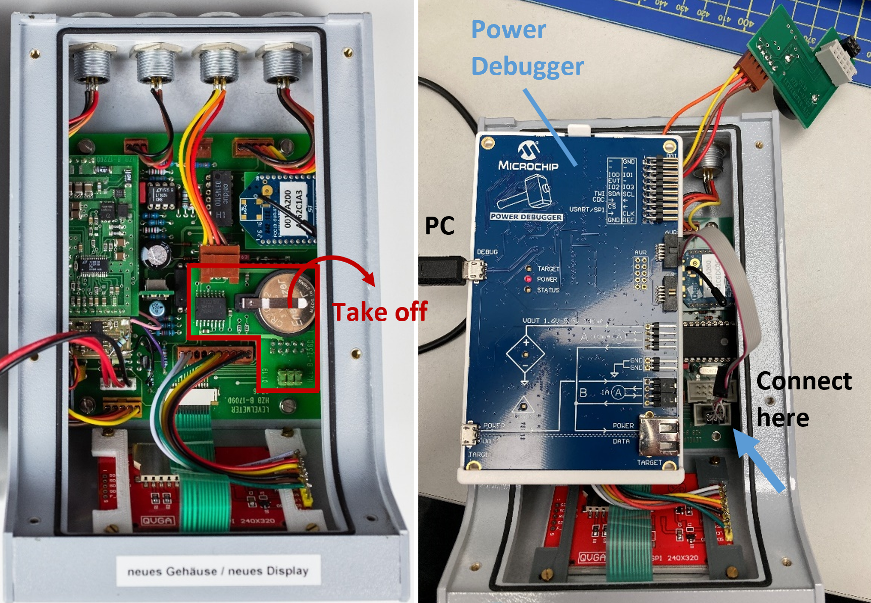
Figure 14: Left: Marked in red is the daughterboard which needs to be removed to uncover the port which the Power Debugger needs to be connected to. Right: The step of connecting the Power Debugger after removing the daughterboard.